30
AUDIO AND VIDEO DOOR ENTRY SYSTEM - ACCESS CONTROL
DESCRIPTION OF THE SOUND MODULES
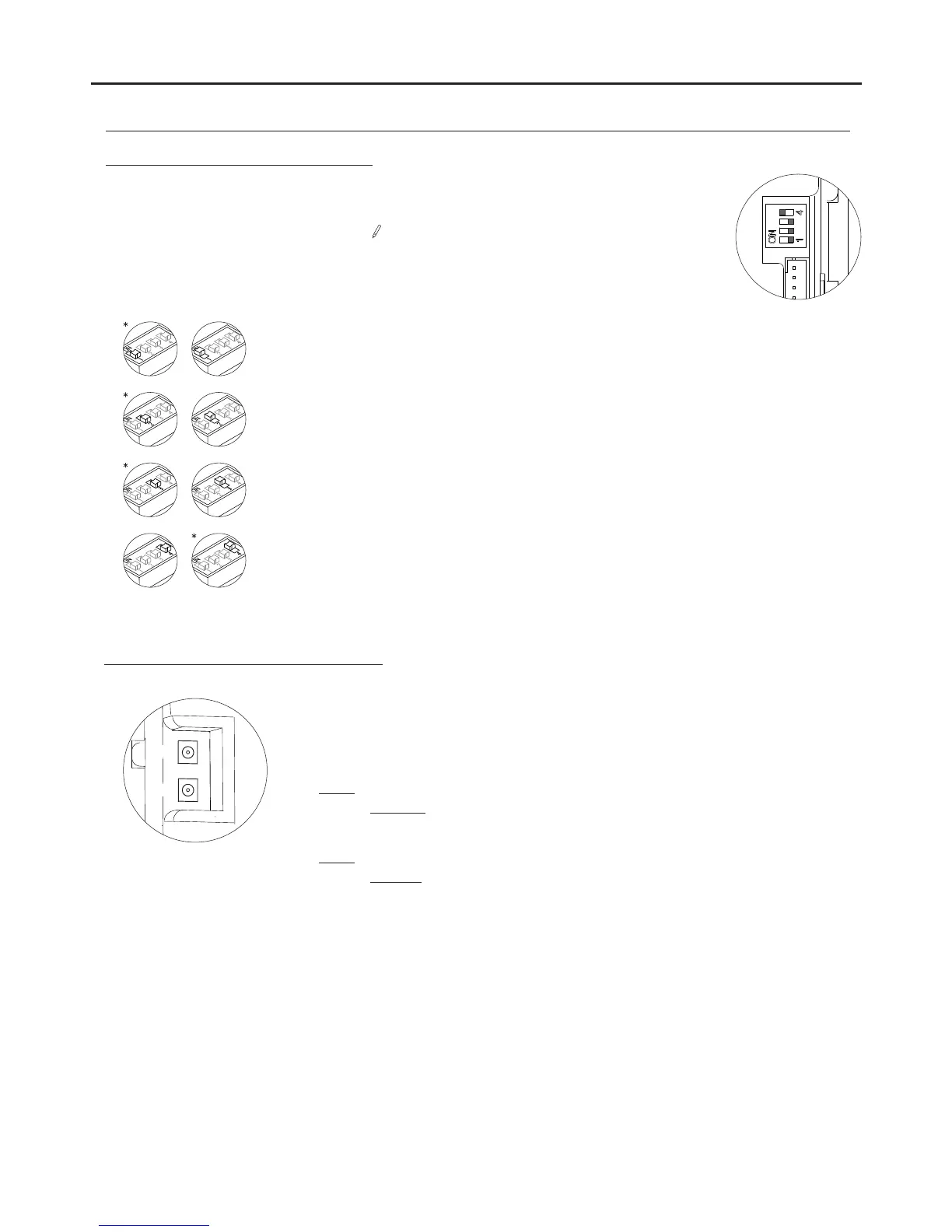
Description of the SW1 DIP switch:
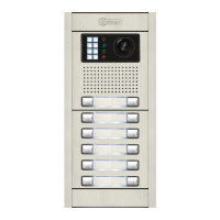
The self-testing LEDs are located on the top left-hand side of
the back of the sound module.
Red LED
Fixed: More than one door panel is configured as the master.
If the sho r t c i rcuit is
eliminated within approx. 2
minutes, the door panel will
automatically reset. After 2
minutes, it will be necessary
to switch the power off and
then on.
Green LED
Fixed: Correct functioning.
Blinking: Door panel is being programmed (DIP switch 2 set to ON).
Blinking: There is a short circuit in the wiring* between the wires of the bus or no
door panel has been configured as the master
.
*
*Factory setting
Set to ON to programme the telephones.
Once the programming has finished, return the switch to the OFF position.
The programming method is described on p. 17.
Set to OFF if it is a master door panel. Each system must have only one master door panel; the
others must be slaves (ON). Set the door panel furthest from the channel as the master. If the
system has a CD-2PLUS converter installed, the maximum number of door panels will be 2 and
these will have to be configured as slaves.
Set to ON to divert calls from the door panel to the guard unit when activated. Set to OFF if this
function is not necessary (CD-2PLUS converter and door panel capture on the guard unit
required).
Set to ON for door panel tone volume or OFF for volumeHIGH LOW
.
Red
Green
Description of the self-testing LEDs:
The SW1 DIP switch is located on the top right-hand side of the back of the module.
To set the DIP switches, use the tool supplied with the sound module.