EasyManua.ls Logo

Graco G3 Series - User Manual

Graco G3 Series
88 pages
To Next Page IconTo Next Page
Loading...
332305J
EN
Instructions
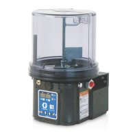
G3 Max Automatic
Lubrication Pump
For dispensing of NLGI Grades #000 to #2 greases and oil with at least 40cSt. For
Professional Use Only.
Not approved for use in explosive atmospheres or hazardous locations.
Part Nos., page 3
5100 psi (35.1 MPa, 351.6 bar) Pump Output Pressure
5000 psi (34.4 MPa, 344.7 bar) Maximum Working Pressure - Auto-Fill Shut Off
Important Safety Instructions
Read all warnings and instructions in this
manual. Save all instructions.
Conforms to ANSI/UL 73
Certified to CAN/CSA
Std. 22.2 No 68-09
3132066
24V and 110-240VAC Pumps ONLY.

Table of Contents

Questions and Answers:

Graco G3 Series Specifications

General IconGeneral
BrandGraco
ModelG3 Series
CategoryWater Pump
LanguageEnglish

Summary

Instructions

Important Safety Instructions

Read all warnings and instructions in this manual. Save all instructions.

Part; Model Numbers

2 Liter Models

List of part numbers and their corresponding model numbers for 2 liter G3 pumps.

4 Liter Models

List of part numbers and their corresponding model numbers for 4 liter G3 pumps.

Understanding the Model Number

Model Number Decoding

Explanation of each component's location and options in the G3 pump model number.

Warnings

Electric Shock Hazard

Hazards related to improper grounding, setup, or usage of the system.

Equipment Misuse Hazard

Risks of death or serious injury due to misuse of the unit.

Skin Injection Hazard

Danger of high-pressure fluid piercing skin, potentially causing amputation.

Pressurized Equipment Hazard

Risk of equipment rupture and serious injury due to over-pressurization.

Personal Protective Equipment

Recommendations for appropriate protective gear to prevent serious injury.

Installation

Unpacking

Procedure for safely unpacking the G3 pump module and inspecting contents.

Choosing an Installation Location

Guidelines for selecting a suitable location for mounting the G3 pump.

Component Identification

Diagram and key identifying major components of the G3 pump.

Typical Installation

Illustrates standard installation methods for divider valve and injector systems.

Optional Installation

Details on installing the pump with or without a remote fill manifold.

System Configuration and Wiring

Grounding

Importance of grounding for safety and preventing static sparking.

Fuses

Information on required fuses for DC models and recommended Graco kit numbers.

Wiring Diagrams

Power DIN AC and DC Connections

Details on pinouts, wire colors, and example wiring for DIN power connections.

Power CPC DC Connections

Details on pinouts, wire colors, and example wiring for CPC DC power connections.

M12 Input Connections

Information on M12 input connectors, pinouts, and example wiring.

Vent Valve and Alarm Outputs

Details on connectors, pinouts, and example wiring for vent valve and alarm outputs.

Setup

Pressure Relief

Procedure for relieving pressure in the system before servicing or maintenance.

Connecting to Auxiliary Fittings

Guidelines for connecting external fittings to the pump without causing damage.

Setting Pump Outlet Volume

Instructions for adjusting the amount of lubricant dispensed per cycle.

Loading Grease

Proper procedures for filling the reservoir with grease.

Auto-Fill Shut Off

Functionality and operation of the auto-fill shut off mechanism for reservoir refilling.

Priming

Steps for priming the pump when it is first used or runs dry.

Max Model Setup

Control Panel Overview

Explanation of the control panel layout, buttons, and display indicators.

Programming the Max Model

Detailed instructions for programming various functions of the Max Model pump.

DMS Models Only

Specific procedures for DMS models, including downloading and storing data.

Operation; Data Log

System Event Log

Lists date and time of common system events like pump cycles and setting changes.

Error Log

Details of logged faults and warnings with set time and clear time.

Functional Summary

Data compiled on pump usage, cycles, faults, and warnings.

Technical Summary

Data on voltage, current, and temperature readings for pump performance.

Advanced Programming

Advanced Programming Options

Table detailing advanced programming options, their settings, format, and purpose.

Entering a PIN Code for the First Time

Instructions for setting up a PIN code to protect pump settings.

A2 - Low Level Alarm Time

Configures time between low level warning and fault to protect unit from running dry.

A3 - Vent Valve Time

Sets the duration the vent valve stays open after a cycle is completed.

A4 - Alarm Retry

Programs the number of automatic retries after a cycle or pressure alarm.

A5 - Active Alarm

Changes alarm output behavior to determine if a fault has occurred.

A6 - Clearing the Functional and Technical User Summary

Clears the functional and technical user summaries for evaluation.

A10 - Low Level Reset Upon Power On

Changes low level fault behavior upon pump power on, allowing self-clearing.

A11 - Warning Off Through Alarm Relay

Changes alarm output behavior in a warning condition to always be off.

A12 - Prelube Sequences

Changes prelube function behavior to add more lubrication sequences upon pump start.

A13- MM:SS OFF Time

Changes the OFF time programming format from HH:MM to MM:SS.

Run Mode

Time Control

Describes how the G3 pump automatically sequences OFF and ON times.

Cycle Control

Controls lubrication cycles based on triggered counts from proximity switches.

Pressure Control

Controls lubrication cycles based on pressure switch activation.

Rest Mode (Pump OFF) Controls

Manages pump rest mode based on machine counts or backup time.

Alarms: Firmware Versions 6.01 and Below

Fault; Warning Scenarios

Details common faults and warnings, their indicators, and solutions.

Low Level Warning

Indicates low lubricant level in reservoir; allows limited operation before alarm.

Low Level Fault

Indicates low lubricant level; stops pumping and displays accumulated time.

Cycle; Pressure Warning

Indicates cycle or lubrication time was not completed; may continue operation.

Cycle; Pressure Fault

Indicates over-pressurization or cycle completion failure; requires manual reset.

Machine Count Fault

Indicates incorrect machine counts received within backup time; requires manual reset.

System Fault

Indicates an internal fault has occurred; requires contact with customer service.

Motor Current Warning

Indicates measured motor current exceeds recommended value; examine system.

Temperature Warning

Indicates internal temperature is outside recommended range; check operating environment.

USB Error

Indicates an error occurred during DMS operation; refer to troubleshooting for details.

Alarms: Firmware Versions 6.02 and Above

Fault; Warning Scenarios

Details common faults and warnings for firmware 6.02+, their indicators, and solutions.

Low Level Warning

Indicates low lubricant level; warning may self-clear after 30 seconds.

Low Level Fault

Indicates low lubricant level; stops pumping and requires manual clear.

Cycle Warning

Indicates cycle time not completed; may continue operation or clear itself.

Pressure Warning

Indicates pressure not relieved within time; may continue operation or clear itself.

Cycle Fault

Indicates cycle completion failure; requires manual reset.

Pressure Fault

Indicates over-pressurization or cycle completion failure; requires manual reset.

Machine Count Warning

Indicates incorrect machine counts received within backup time; requires manual reset.

Machine Count Fault

Indicates incorrect machine counts received within backup time; requires manual reset.

System Fault

Indicates an internal fault has occurred; requires contact with customer service.

Motor Current Warning

Indicates motor current exceeds recommended value; examine system for issues.

Temperature Warning

Indicates internal temperature is outside recommended range; check operating environment.

USB Error

Indicates an error during DMS operation; refer to troubleshooting for details.

Fault;Warning Scenarios for Firmware Versions 6.06 and Later for Non-DMS Models and 7.09 and later for DMS Models

Low Power Warning

Indicates a voltage drop at the power source; allows limited operation before fault.

Low Power Fault

Indicates low voltage at power source; requires manual reset to clear fault.

Troubleshooting

Common Troubleshooting Scenarios

Addresses common problems like no power, incorrect times, leaks, and pump issues.

USB Troubleshooting

Details troubleshooting steps for USB errors, including file and connection issues.

Maintenance

Daily Maintenance

Routine cleaning of fittings, pump unit, reservoir, and display.

Monthly Maintenance

Verification of external wiring harness security.

Parts - 2 Liter Models

2 Liter Model Components

Diagram and list of parts for 2 liter G3 pump models.

Parts - 4 Liter and Larger Models

4 Liter and Larger Model Components

Diagram and list of parts for 4 liter and larger G3 pump models.

Parts List

Fuses

Details on fuse types and part numbers for G3 pumps.

Installation and Repair Kits

Catalog of available kits for installation and repair of G3 pumps.

Technical Data

Pump Specifications

Technical specifications for pump output, power, voltage, current, and inputs.

Fluid and Dimension Data

Information on compatible fluids, reservoir sizes, weight, and physical dimensions.

Mounting Pattern

Diagrams illustrating mounting configurations (Option 1 and Option 2).

Graco Standard Warranty

Graco Information

Contact information and website for Graco products and support.

Related product manuals