English (GB)
10
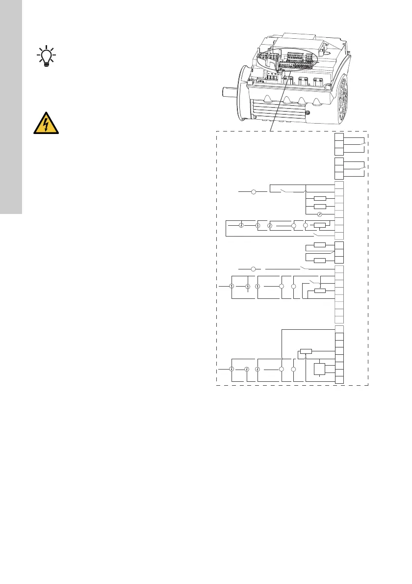
• Inputs and outputs
All inputs and outputs are internally separated from
the mains-conducting parts by reinforced insulation
and galvanically separated from other circuits. All
control terminals are supplied by protective extra-low
voltage (PELV), thus ensuring protection against
electric shock.
• Signal relay outputs
– Signal relay 1:
LIVE:
You can connect supply voltages up to 250
VAC.
PELV:
The output is galvanically separated from
other circuits. Therefore, you can connect the
supply voltage or protective extra-low voltage
to the output as desired.
– Signal relay 2:
PELV:
The output is galvanically separated from
other circuits. Therefore, you can connect the
supply voltage or protective extra-low voltage
to the output as desired.
• Mains supply (terminals N, PE, L or L1, L2, L3,
PE).
* If you use an external supply source, there must
be a connection to GND.
Fig. 8 Connection terminals, CRE, CRIE,
CRNE, SPKE and MTRE pumps
Digital input 1 is factory-set to be start-stop
input where open circuit results in stop. A
jumper has been factory-fitted between
terminals 2 and 6. Remove the jumper if
digital input 1 is to be used as external
start-stop or any other external function.
DANGER
Electric shock
- Death or serious personal injury
- Make sure that the wires to be
connected to the connection groups
below are separated from each other by
reinforced insulation in their entire
lengths.
TM05 3509 3512
3
15
8
26
23
25
24
7
21
20
22
B
Y
6
5
2
4
10
A
+24 V*
1
14
9
12
17
19
11
18
+24 V*
+
+24 V*
OC
DI
+24 V*/5 V*
+24 V*
+
+
+
+24 V*/5 V*
+24 V*
+24 V*
+
+
+24 V*/5 V*
+24 V*
+5 V*
AI2
GDS RX
GDS TX
GND
GENIbus A
GENIbus B
+5 V
+24 V
+24 V
GND
GENIbus Y
GND
+5 V
DI1
AI1
DI3/OC1
LiqTec
AI3
GND
DI2
LiqTec
GND
AO
Pt100/1000
Pt100/1000
DI4/OC2
GND
+24 V*
OC
DI
GND
NC
C2
NO
NC
C1
NO
+5 V*
 Loading...


