English (GB)
14
7.6 Signal cables
• Use screened cables with a cross-sectional area
of minimum 0.5 mm
2
and maximum 1.5 mm
2
for
the external on/off switch, digital inputs, setpoint
and sensor signals.
• Connect the screens of the cables to the frame at
both ends with good connection. The screens
must be as close as possible to the terminals.
See fig. 10.
Fig. 10 Stripped cable with screen and wire
connections
• Always tighten screws for frame connections
whether a cable is fitted or not.
• The wires in the motor terminal box must be as
short as possible.
7.7 Bus connection cable
7.7.1 New installations
For the bus connection, use a screened 3-core cable
with a cross-sectional area of minimum 0.5 mm
2
and
maximum 1.5 mm
2
.
If the motor is connected to a unit with a cable clamp
which is identical to the one on the motor, connect
the screen to this cable clamp.
If the unit has no cable clamp leave the screen
unconnected at this end. See fig. 11.
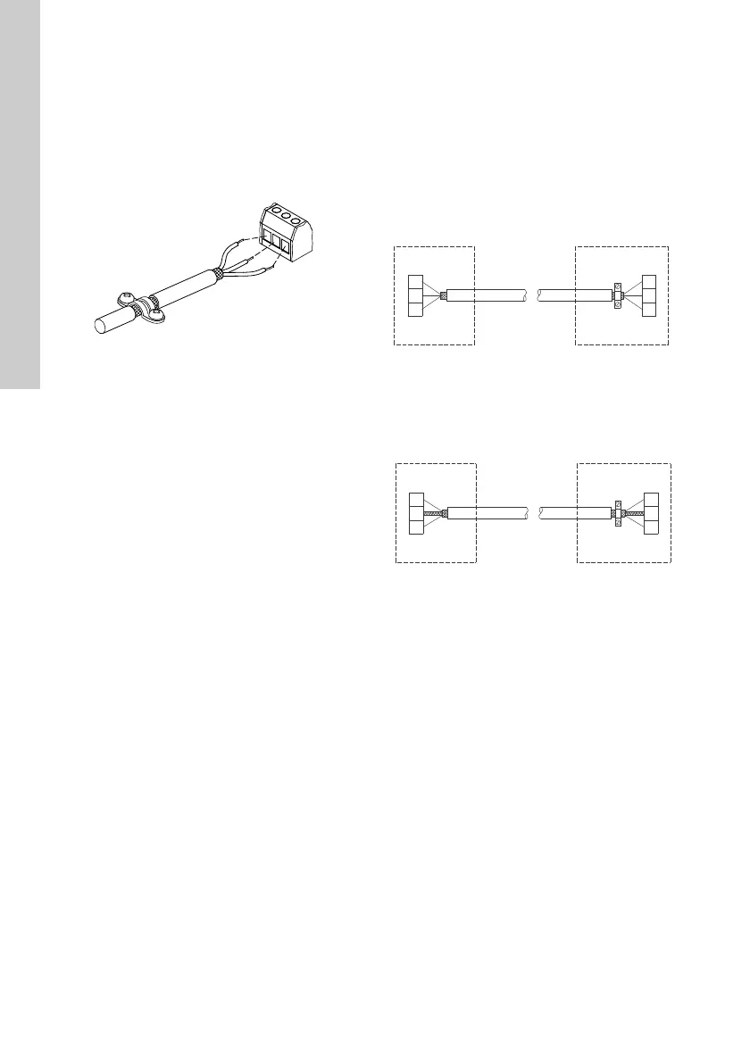
Fig. 11 Connection with screened 3-core cable
7.7.2 Replacing a motor
• If a 2-core cable is used in the installation,
connect it as shown in fig. 12.
Fig. 12 Connection with screened 2-core cable
• If a screened 3-core cable is used in the
installation, follow the instructions in section
7.7.1 New installations.
TM02 1325 4402
TM05 3973 1812TM02 8842 0904