English (GB)
37
13.9 Digital inputs/outputs
Available inputs/outputs depend on the functional
module fitted in the pump:
* See section 19. Identification of functional
module.
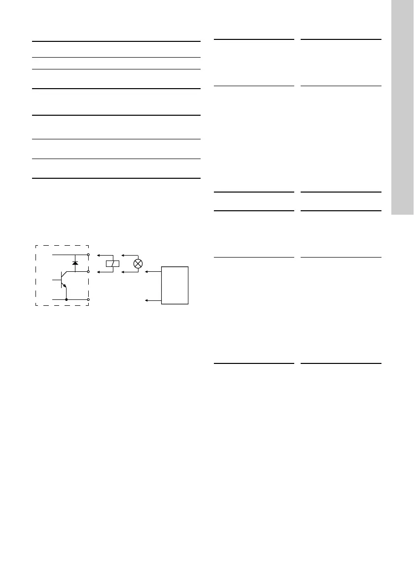
You can select if the interface is to be used as input
or output. The output is an open collector and you
can connect it to e.g. an external relay or controller
such as a PLC.
Fig. 42 Example of configurable digital
inputs/outputs
To set a digital input/output, make the settings below.
Mode
You can set the digital input/output 3 and 4 to act as
digital input or digital output:
• Digital input
• Digital output.
Function
You can set the digital input/output 3 and 4 to the
functions stated in the table below:
Possible functions, digital input/output 3
Possible functions, digital input/output 4
Activation delay (only for input)
Select the activation delay (T1).
It is the time between the digital signal and the
activation of the selected function.
Range: 0-6000 seconds.
Pump variant Digital inputs/outputs
CME ●
CRE, CRIE, CRNE,
SPKE, MTRE
●
Function (terminal)
FM 200*
(standard)
FM 300*
(advanced)
Digital input/output 3,
setup (6 and 10)
●●
Digital input/output 4,
setup (11 and 18)
- ●
TM06 4463 2315
Function if input
(See details in
section 13.8 Digital
inputs)
Function if output
(See details in
section 13.10 "Signal
relays" 1 and 2 (Relay
outputs))
• Not active
• External stop
•Min.
•Max.
• "User-defined
speed"
• External fault
• Alarm resetting
• Dry running
• Accumulated flow
• Predefined setpoint
digit 2
•Not active
• Ready
•Alarm
• Operation
• Pump running
• Warning
• Limit 1 exceeded
• Limit 2 exceeded
Function if input
(See details in
section 13.8 Digital
inputs)
Function if output
(See details in
section 13.10 "Signal
relays" 1 and 2 (Relay
outputs))
• Not active
• External stop
•Min.
•Max.
• "User-defined
speed"
• External fault
• Alarm resetting
• Dry running
• Accumulated flow
• Predefined setpoint
digit 3
•Not active
• Ready
•Alarm
• Operation
• Pump running
• Warning
• Limit 1 exceeded
• Limit 2 exceeded