English (GB)
43
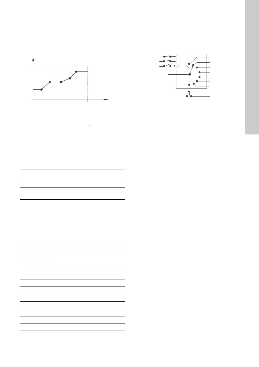
• Influence table.
The setpoint is influenced by a curve made out of
two to eight points. There is a straight line
between the points and a horizontal line before
the first point and after the last point.
Fig. 49 Influence table (example with five
points)
Factory setting
See section 24. Factory settings.
13.15 Predefined setpoints
You can set and activate seven predefined setpoints
by combining the input signals to digital inputs 2, 3
and 4. See the table below.
Set the digital inputs 2, 3 and 4 to Predefined
setpoints if all seven predefined setpoints are to be
used. You can also set one or two of the digital inputs
to Predefined setpoints but this limits the number of
predefined setpoints available.
Example
Figure 50 shows how you can use the digital inputs
to set seven predefined setpoints. Digital input 2 is
open and digital inputs 3 and 4 are closed. If you
compare with the table above, you can see that
Predefined setpoint 6 is activated.
Fig. 50 Principle sketch showing how
predefined setpoints function
If all digital inputs are open, the pump stops or runs
at the normal setpoint. Set the desired action with
Grundfos GO or with the advanced control panel.
Factory setting
See section 24. Factory settings.
TM06 4170 1615
Pump variant Predefined setpoints
CME -
CRE, CRIE, CRNE,
SPKE, MTRE
●
Digital
inputs
Setpoint
234
0 0 0 Normal setpoint or stop
1 0 0 Predefined setpoint 1
0 1 0 Predefined setpoint 2
1 1 0 Predefined setpoint 3
0 0 1 Predefined setpoint 4
1 0 1 Predefined setpoint 5
0 1 1 Predefined setpoint 6
1 1 1 Predefined setpoint 7
0: Open contact
1: Closed contact
100
0
100 %0
3.5 V0.5
5 V0
10 V0
20 mA0
20 mA4
Setpoint influence [%]
External
input
TM06 4269 1815
Digital input 4
Setpoint 1
Setpoint 2
Setpoint 3
Setpoint 4
Setpoint 5
Setpoint 6
Setpoint 7
Digital input 3
Digital input 2
Actual setpoint
Stop
Normal
setpoint