English (GB)
38
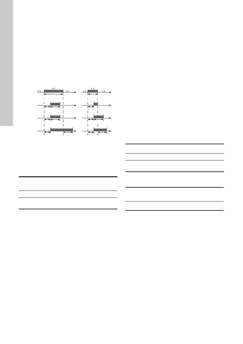
Duration timer mode (only for input)
Select the duration timer mode. See fig. 41.
•Not active
• active with interrupt (mode A)
• active without interrupt (mode B)
• active with after-run (mode C)
Select the duration time (T2).
It is the time which, together with the mode,
determines how long the selected function is active.
Range: 0 to 15,000 seconds.
Fig. 43 Duration timer function of digital inputs
Factory setting
See section 24. Factory settings.
13.10 "Signal relays" 1 and 2 (Relay
outputs)
The pump incorporates two signal relays for
potential-free signalling. For further information, see
section 25. Megging.
Function
You can configure the signal relays to be activated
by one of the following incidents:
•Not active.
• Ready.
The pump can be running or is ready to run and
no alarms are present.
•Alarm.
There is an active alarm and the pump is
stopped.
• "Operating" (Operation).
"Operating" equals "Running" but the pump is still
in operation when the pump is stopped due to low
flow. See section "Low-flow detection" on page
46.
• "Running" (Pump running).
The pump is running.
• Warning.
There is an active warning.
• Limit 1 exceeded
When this function is activated, the signal relay is
activated. See section 13.16 Limit-exceeded
function.
• Limit 2 exceeded.
When this function is activated, the signal relay is
activated. See section 13.16 Limit-exceeded
function.
• "External fan control" (Control of external fan).
When you select "External fan control", the relay
is activated if the internal temperature of the
motor electronics reach a preset limit value.
Factory setting
See section 24. Factory settings.
13.11 Analog output
Whether the analog output is available or not,
depends on the functional module fitted in the pump:
* See section 19. Identification of functional
module.
The analog output enables the reading of certain
operating data to external control systems.
To set the analog output, make the settings below.
Output signal
• 0-10 V
• 0-20 mA
• 4-20 mA.
TM06 4949 3415
Pump variant
"Signal relays" 1 and 2
(Relay outputs)
CME ●
CRE, CRIE, CRNE,
SPKE, MTRE
●
T input
T input > T1 + T2 T input < T1 + T2
T1 T2
T1 T2
T1 T1 T2T2
T1
T1
T input
T2
Mode C
Mode B
Mode A
Digital
input
T input > T1 + T2
T input < T1 + T2
T input
T input
Pump variant Analog output
CME ●
CRE, CRIE, CRNE,
SPKE, MTRE
●
Function (terminal)
FM 200*
(standard)
FM 300*
(advanced)
Analog output - ●