7
English (US)
4. Installing the product
All installations must be performed by personnel experienced with
the placement, connection, and alignment of pumping equipment.
The following instructions are general in nature, and may not deal
with the specifics of your installation. Read these instructions
thoroughly before installing and operating your KP, KPV, or KPVS
pump.
4.1 Location
• Locate the pump as close as possible to the liquid supply. Use
the shortest and most direct inlet pipe practical. Refer to
section 4.4.2 Inlet pipe.
• Locate the pump below system level wherever possible. This
will facilitate priming, assure a steady liquid flow, and provide
a positive inlet pressure.
• The Net Positive Suction Head (NPSH) available must always
be equal to or exceed the required NPSH specified on the
pump performance curve. Make sure that sufficient NPSH is
provided at the inlet.
• Always allow sufficient accessibility space for maintenance
and inspection. Provide a clearance of 24 in. (610 mm) with
ample head room for use of overhead lifting equipment strong
enough to lift the product.
• Do not expose the product to sub-zero temperatures to
prevent the pumped liquid from freezing. If there is frost during
shutdown periods, see the shutdown information included in
section 8.8 Taking the product out of operation.
4.2 Pump foundation
Install the pump permanently on a firm, raised concrete
foundation of sufficient size to dampen any vibration and prevent
any deflection or shaft misalignment. The foundation may float on
springs or be a raised part of the floor.
Proceed like this:
1. Pour the foundation without interruption to 0.75 - 1.5 in. (20-
35 mm) below the final pump level.
2. Scour and groove the top surface of the foundation before the
concrete sets to provide a suitable bonding surface for the
grout.
3. Place anchor bolts in pipe sleeves for positioning allowance.
See fig. 5 and fig. 6.
4. Allow enough bolt length for grout, base, flange, nuts, and
washers.
5. Allow the foundation to cure several days before proceeding
to install the pump.
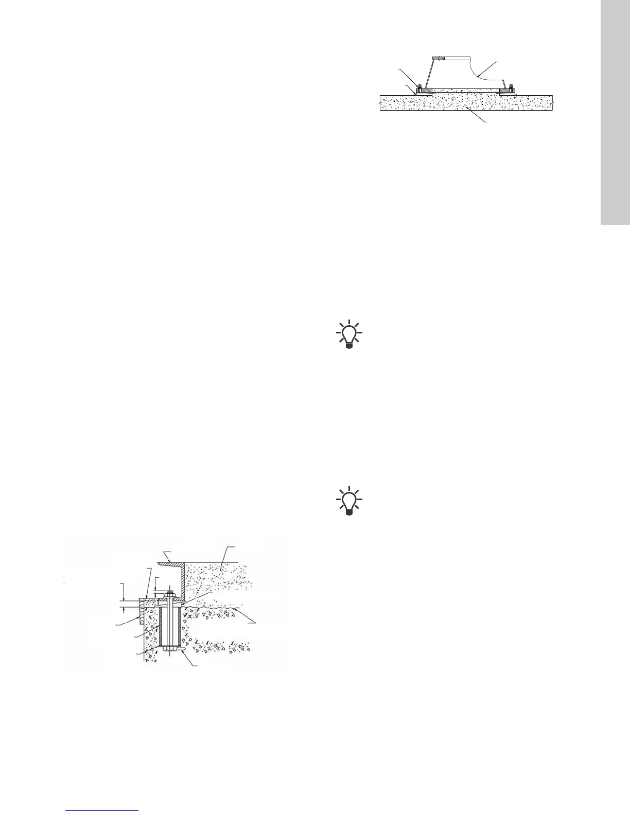
Fig. 5 KP anchor bolt installation
Fig. 6 KPV, KPVS anchor bolt installation
4.3 Securing the baseplate
When the raised concrete foundation has been poured and
allowed to set, proceed as follows:
1. Lower the base plate over the anchor bolts and rest it on loose
adjustment wedges or shims placed near each anchor bolt
and at intervals not exceeding 24 in. (610 mm) along each
side.
2. Place the shims or wedges so that they raise the bottom of the
base plate 0.75 in. - 1.25 in. (20-32 mm) above the pad,
allowing clearance for grout.
3. Level the pump shaft, flanges, and base plate using a spirit
level, adjusting the wedges or shims, as required.
4. Make sure that the pipes can be aligned to the pump flanges
without placing any strain on either flange.
5. After pump alignment has been established, put nuts on
anchor bolts and tighten them just enough to keep the base
plate from moving.
6. Construct a formwork around the concrete foundation and
pour grout inside and around the base plate. See fig. 5 for KP
and fig. 6 for KPV, KPVS. The grout will compensate for
uneven foundation, distribute the weight of the pump, and
prevent shifting.
7. Allow at least 24 hours for the grout to set before proceeding
with the pipe connections.
8. After the grout has thoroughly hardened, check the anchor
bolts and tighten them if necessary. Recheck the pump
alignment after tightening the anchor bolts.
TM05 4775 2512
Grout
Base plate
Finished grouting
0.75 to 1.25 in.
(20 to 32 mm)
allowance for
grout
Formwork
Pipe sleeve
Washer
Lug
Top of foundation
Wedges or shims
left in place
0.25
TM06 6124 0816
Place a spirit level on top of the pump to check that it
is level.
Use an approved, non-shrinking grout.
KPV, KPVS
stand
Anchor bolts for
supporting the base
Wedges or shims
(as required)
Grouted pad for
anchoring/
housekeeping