8
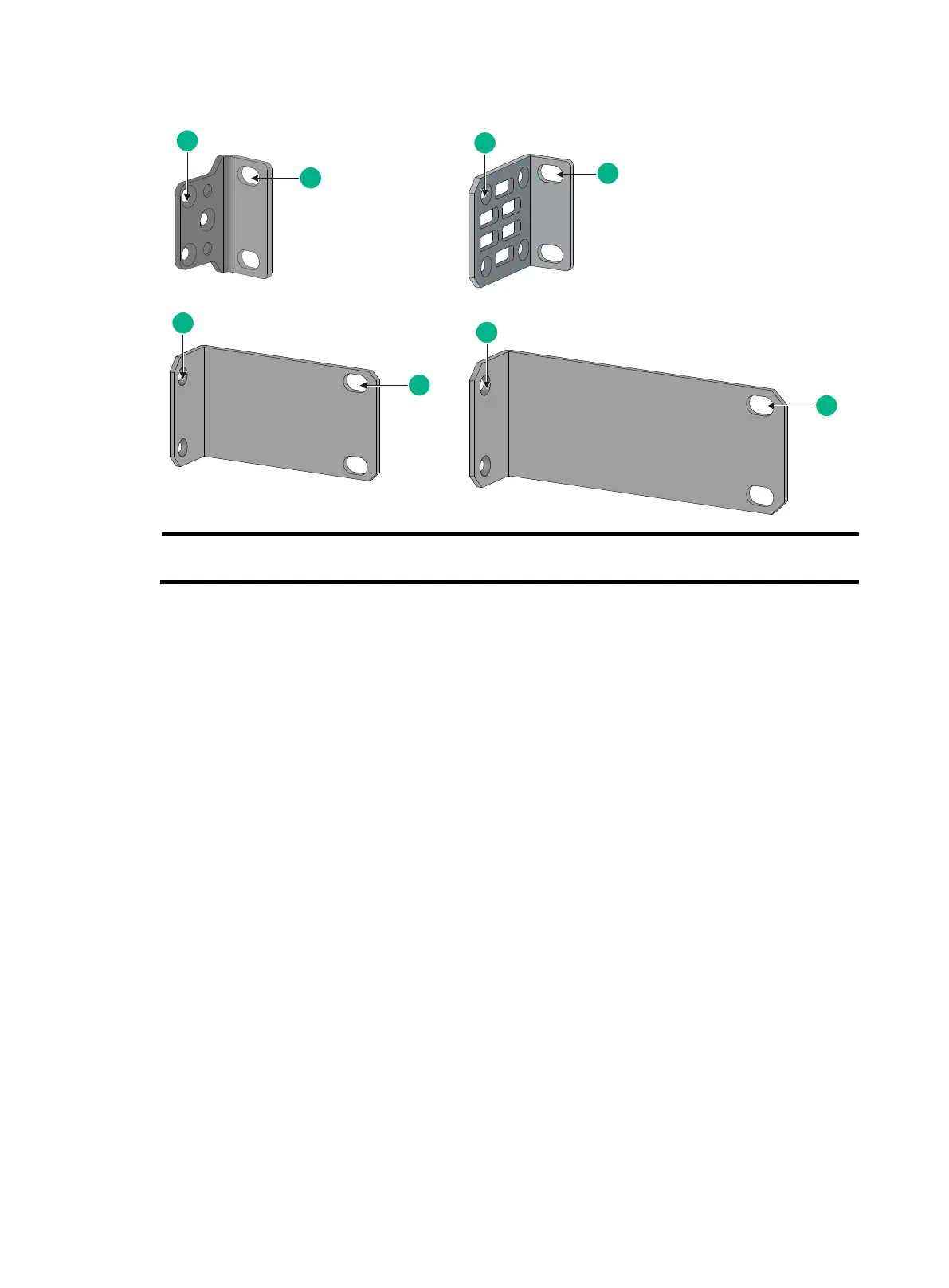
Figure 2 Mounting brackets
(1) Screw hole for attaching the bracket to the switch
(2 ) Screw hole for attaching the bracket to the rack post
Attaching the mounting brackets to the switch
1. Determine the installation position for the mounting brackets.
The S5560S-28F-SI, S5560S-28DP-SI, and S5130S-28F-SI switches each provide two
mounting positions on the two sides for mounting brackets: one front mounting position
(near the network ports) and one rear mounting position (near the power modules).
The other switch models provide only one mounting position (near the network ports) for the
mounting brackets.
2. Align one mounting bracket with the screw holes at the mounting position. Use M4 screws to
attach the mounting bracket to the chassis. See Figure 3 for installing mounting bracket A,
Figure 4 and Figure 5 for installing mounting bracket B, Figure 6 for installing mounting bracket
C, and Figure 7 for installing mounting bracket D.
M4 screws are provided only for switches shipped with mounting brackets.
An optional mounting bracket kit contains M4 screws.
3. Repeat step 2 to attach the other mounting bracket to the chassis.