46
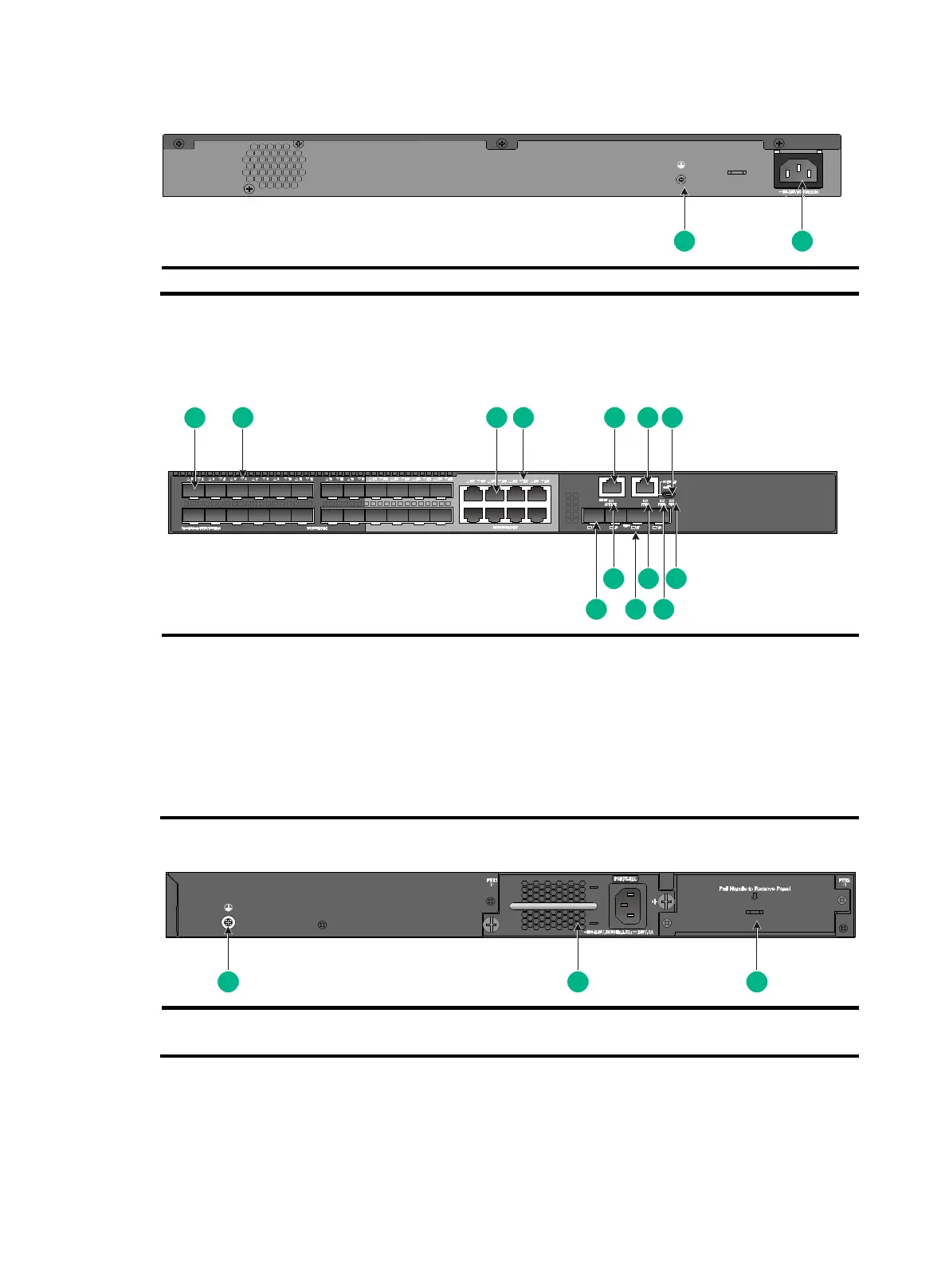
Figure 55 Rear panel
(2) AC-input power receptacle
S5130S-28F-SI
Figure 56 Front panel
(3) 10/100/1000BASE-T autosensing Ethernet port
(4) 10/100/1000BASE-T autosensing Ethernet port LED
(5) Management Ethernet port
(6) Console port (CONSOLE)
(7) Micro USB console port
(8) System status LED (SYS)
(9) Power module 2 status LED (PWR2)
(10) Power module 1 status LED (PWR1)
(12) Management Ethernet port LED (ACT/LINK)
Figure 57 Rear panel
(2) Power module slot 1 (PWR1)
(3) Power module slot 2 (PWR2)
An S5130S-28F-SI switch comes with power module slot 1 installed with a PSR75-12A and power
module slot 2 installed with a filler panel. For information about installing and removing a power
module, see "Installing and removing a power module."