Quick Start
H3C S5500-EI Series Ethernet Switches
Chapter 3 Installation
3-19
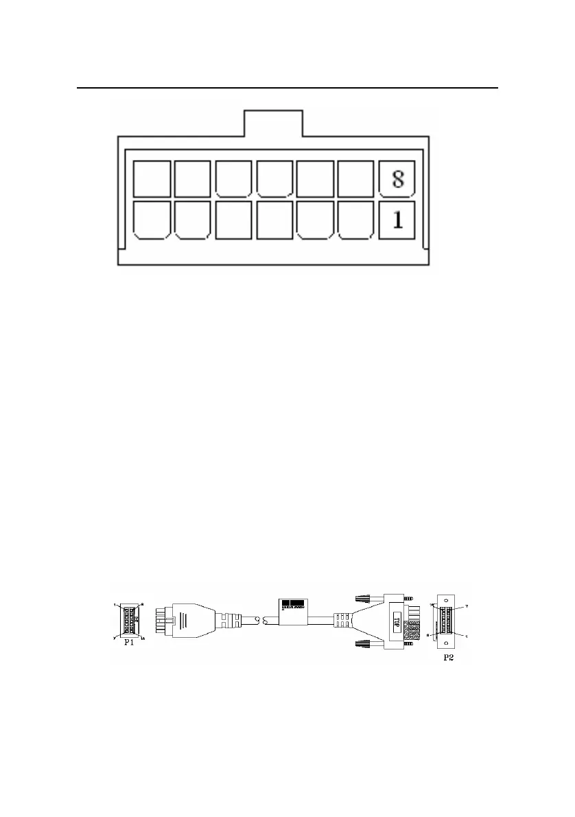
Pin Number Designation Pin Number Designation
1 GND 8 GND
2 -50V 9 -50V
3 12V 10 RPS_pres
4 12V 11 -50Vrtn
5 12V 12 -50Vrtn
6 12V 13 Control Pin
7 GND 14 GND
Figure 3-17 Appearance of the 12V RPS socket
Connect the DC power cable of the S5500-28C-EI and
S5500-52C-EI as follows:
1) Connect one end of the grounding cable to the grounding
screw on the rear panel and the other end to the ground as
near as possible.
2) Connect the 12V RPS power connectors.
Figure 3-18 12V RPS power cable
 Loading...


