Quick Start
H3C S5500-EI Series Ethernet Switches
Chapter 3 Installation
3-29
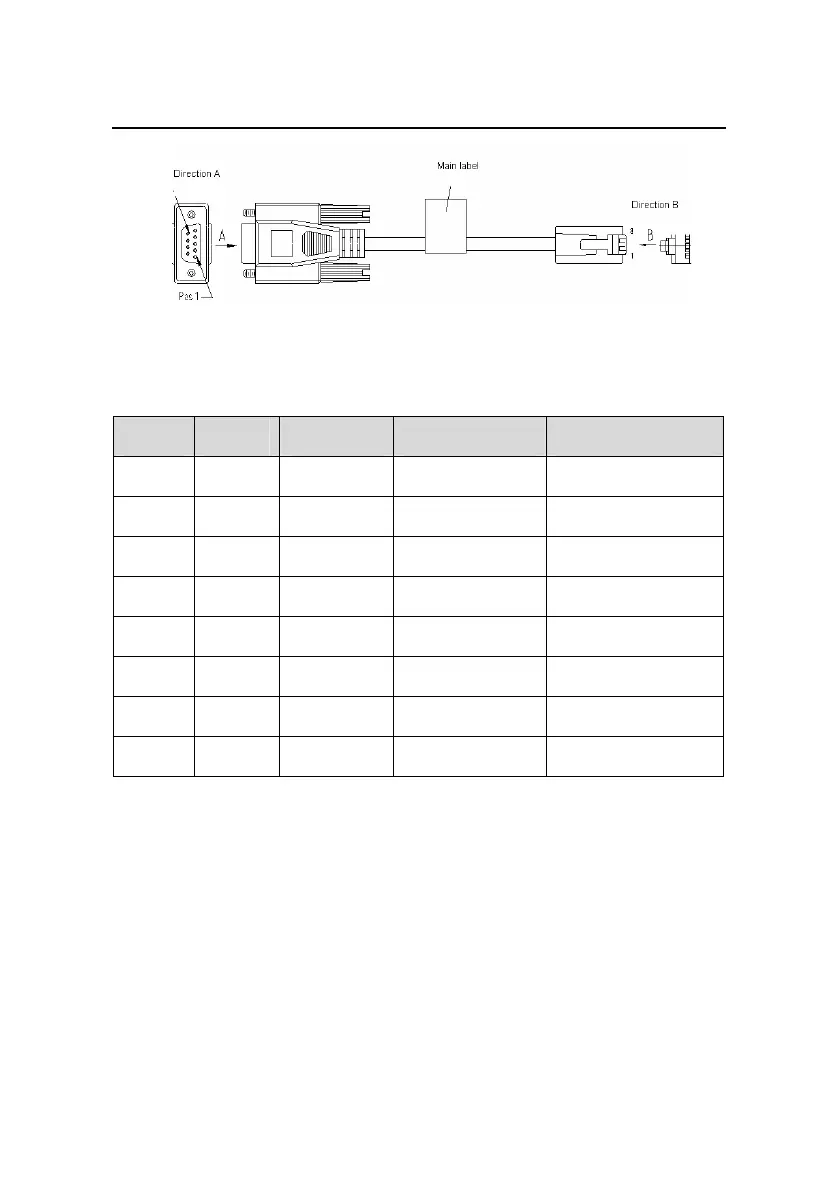
Figure 3-30 Console cable
Table 3-3 Console cable pinouts
RJ-45 Signal Direction DB9(MODEM) DB9(CONSOLE)
1 RTS → 7 8
2 DTR → 4 6
3 TXD → 3 2
4 CD ← 1 5
5 GND — 5 5
6 RXD ← 2 3
7 DSR ← 6 4
8 CTS ← 8 7
3.4.2 Connection Procedure
When you want to use the terminal to configure the switch, follow
these steps to connect a terminal device to the switch using the
console cable:
 Loading...


