Quick Start
H3C S5500-EI Series Ethernet Switches
Chapter 3 Installation
3-5
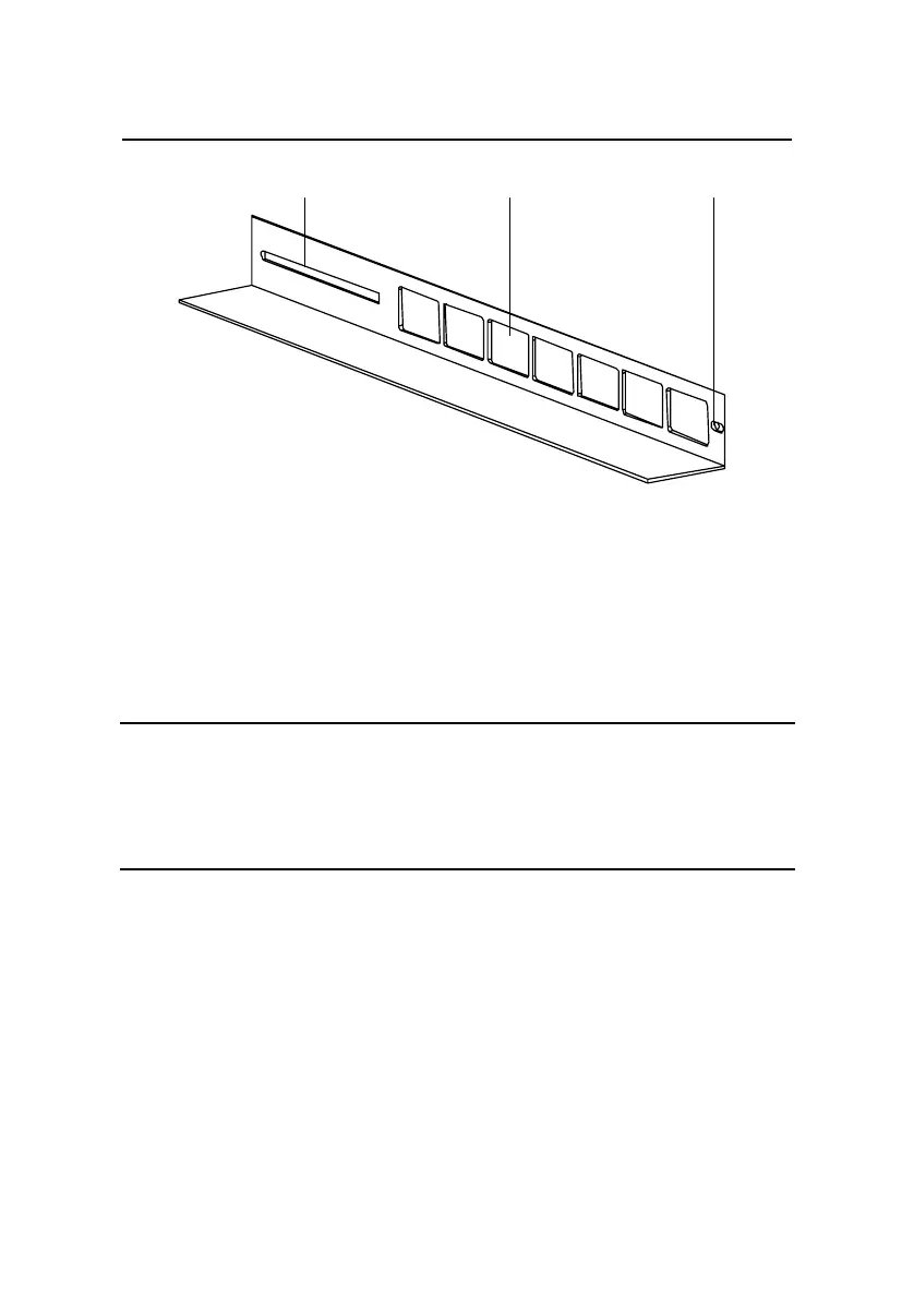
Slotted hole 1 Cooling hole Slotted hole 2
Slotted hole 1: Used to fix the guide rail to the rear bracket. You can adjust
the screw hole position according to the position of the switch.
Cooling hole: Used for heat dissipation between switch and cabinet
Slotted hole 2: Used to fix the guide rail to the front bracket
Figure 3-3 Appearance of a guide rail
Note:
Guide rails are optional parts. Check Table 3-1 to see whether you
need to order them or not.
3.1.3 Using Front Mounting Ears to Install the Switch
Follow these steps to install the switch into a 19-inch standard
cabinet:
1) Wear an ESD-preventive wrist strap to check the grounding
and stability of the cabinet.
 Loading...


