Quick Start
H3C S5500-EI Series Ethernet Switches
Chapter 3 Installation
3-23
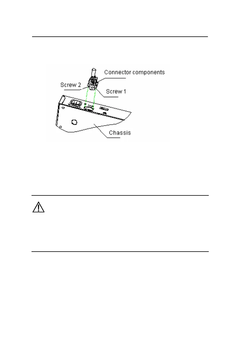
two screws (delivered with the switch), as shown in Figure
3-23.
Figure 3-23 Connect the 48V RPS connector to the chassis
3) Check whether the RPS LED on the front panel of the switch
is ON. If the LED is ON, the 48V RPS is properly connected.
Caution:
z Make sure that the grounding cable has been properly connected
before powering on the switch.
z The length of the DC power cable must be less than 3 m (9.8 ft).
 Loading...


