Quick Start
H3C S5500-EI Series Ethernet Switches
Chapter 3 Installation
3-26
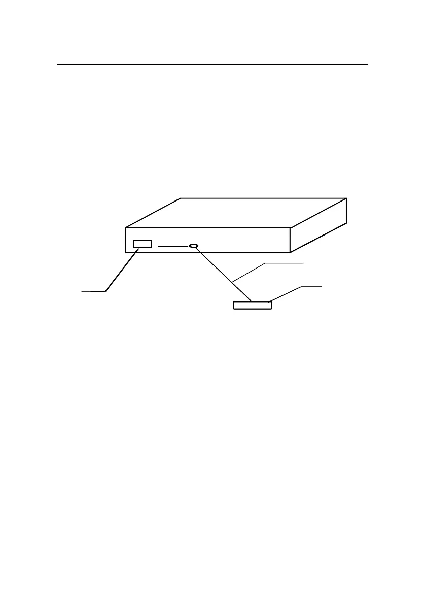
z When a grounding strip is available at the installation site,
attach one end of the yellow-green grounding cable of the
switch to the grounding terminal on the grounding strip and
fasten the captive nut. Note that the fire main and lightning
rod of a building are not suitable for grounding. The
grounding cable of the switch should be connected to the
grounding system in the equipment room.
(1)
(2)
(3)
(4)
(1)
(2)
(3)
(4)
(1) AC power socket (2) Grounding terminal
(3) Protection grounding cable (4) Grounding strip
Figure 3-26 Ground the switch through a grounding strip
z When there is no grounding strip but earth is available near
the installation location and allows a grounding body to be
buried, hammer an angle iron/steel pipe longer than 0.5 m
(1.64 ft) into the earth. Weld the yellow-green grounding
cable of the switch onto the angle iron/steel pipe, and treat
the joint for corrosion protection.
 Loading...


