Quick Start
H3C S5500-EI Series Ethernet Switches
Chapter 3 Installation
3-21
a) As shown in Figure 3-20, loosen the fastening screws and
remove the RPS connector cover from the 12V RPS port.
(If no 12V RPS power supply is connected, install the
cover.)
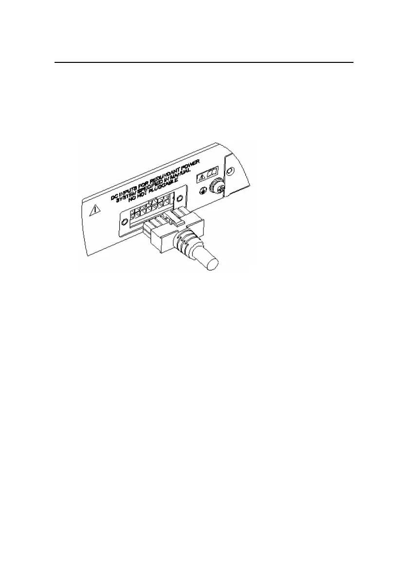
Figure 3-21 Connect the 12V RPS connector to the chassis
b) Connect one connector (in the p1 direction) of the 12V
RPS power cable to the RPS port on the switch, making
sure that the protruding part is inserted into the
positioning slot, as shown in
Figure 3-21. Connect the
other connector (in the p2 direction) to the power socket
of the RPS power module.
c) Connect one end of the AC power cable (delivered with the
RPS) to the power socket of the RPS power module and
the other end to the socket of an external AC power
supply.
3) Check whether the RPS LED on the front panel of the switch
is ON. If yes, the power supply is properly connected.
 Loading...


