Quick Start
H3C S5500-EI Series Ethernet Switches
Chapter 3 Installation
3-11
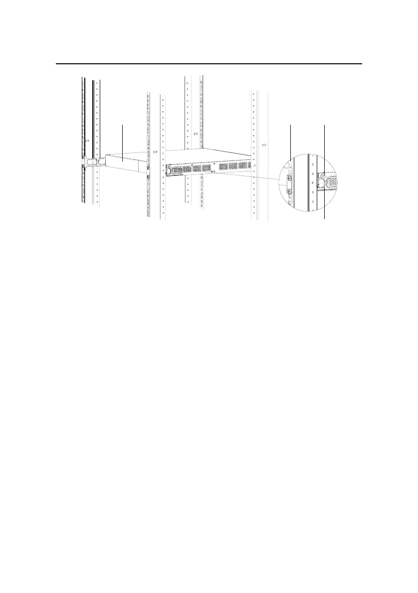
Rear panel
Rear square-
holed bracket
Screw 1
Rear mounting ear
Screw 1: Load-bearing screw
Figure 3-9 Effect diagram of front and rear mounting ear
installation (1)
6) Fix the other end of the front mounting ears to the front
brackets with screws and captive nuts and ensure that front
and rear mounting ears have fixed the switch in the cabinet
securely, as shown in
Figure 3-10.
 Loading...


