Quick Start
H3C S5500-EI Series Ethernet Switches
Chapter 3 Installation
3-3
(1) (2)
L1
L2
(1) Screw hole used to fix the mounting ear to the cabinet (Use one M6
screw)
(2) Screw hole used to fix the switch to the mounting ear
Figure 3-1 Appearance of a standard front mounting ear
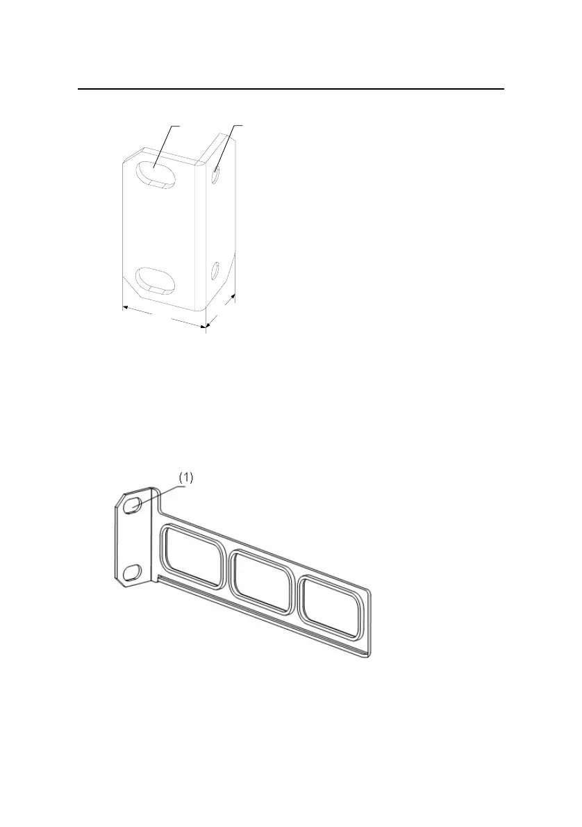
Figure 3-2 shows the appearance of a rear mounting ear.
(1) Screw hole used to fix the mounting ear to the cabinet (Use one M6
screw)
Figure 3-2 Appearance of a rear mounting ear
 Loading...


