Quick Start
H3C S5500-EI Series Ethernet Switches
Chapter 3 Installation
3-12
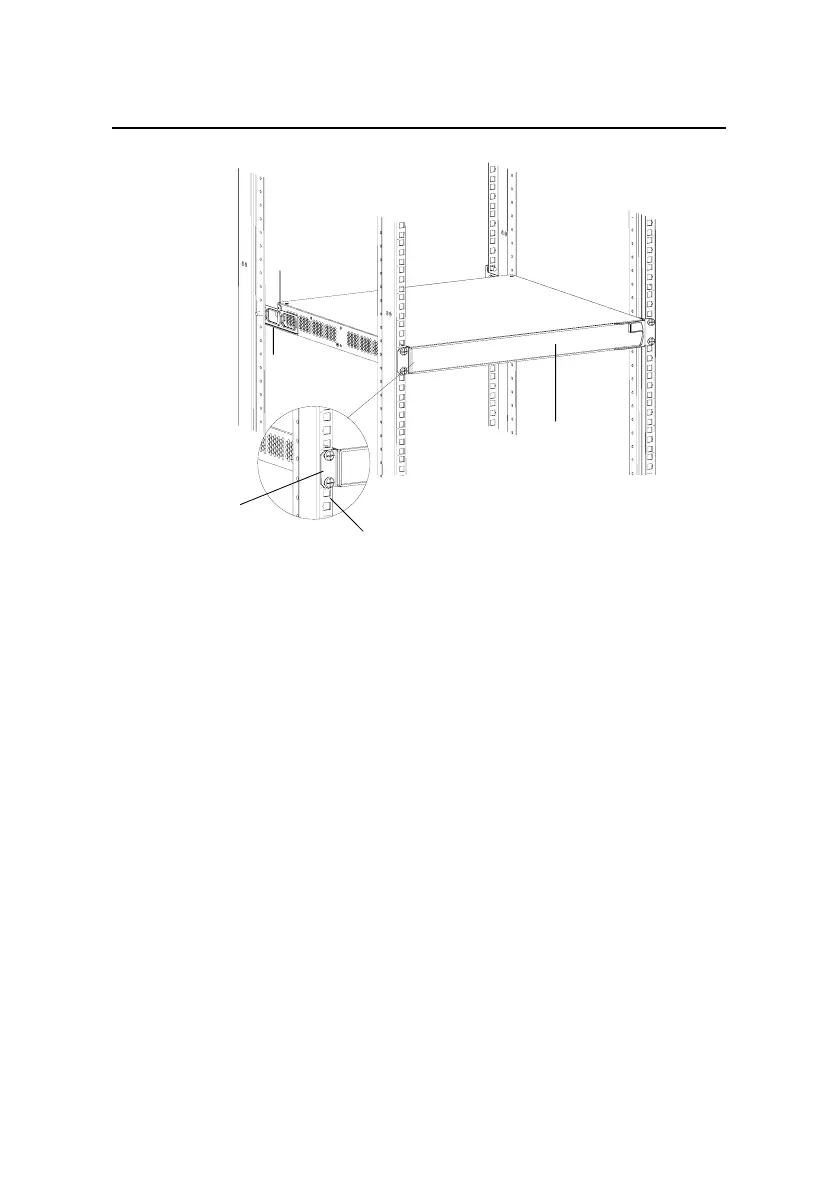
Front panel
Screw 1
Rear
mounting ear
Front square-holed bracket
Front mounting ear
Screw 1: Load-bearing screw
Figure 3-10 Effect diagram of front and rear mounting ear
installation (2)
3.1.6 Using Front Mounting Ears and Guide Rails
Follow these steps to install a switch into a 19-inch standard
cabinet:
1) Wear an ESD-preventive wrist strap to check the grounding
and stability of the cabinet.
2) Take out the screws packed together with the front mounting
ears and fix one end of the front mounting ears to the switch,
as shown in
Figure 3-4.
 Loading...


