60
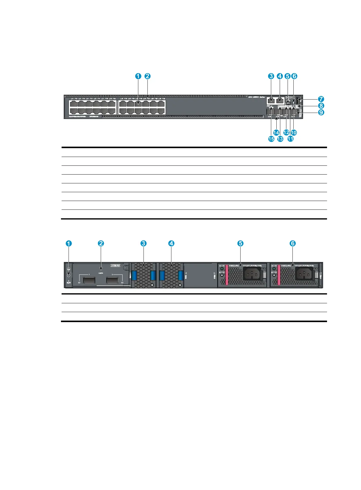
S5560-30C-PWR-EI
Figure 70 S5560-30C-PWR-EI front panel
(1) 10/100/1000BASE-T autosensin
Ethernet port
(2) 10/100/1000BASE-T
autosensin
Ethernet port LED
(3) Mana
ement Ethernet port (4) Console
port
(CONSOLE)
(5) Mini USB console port (6) Port LED mode switching button
(7) USB port (8) System status LED (SYS)
(9) SFP+ port (10) LED for the port LED mode (MODE)
(11) Expansion card status LED (SLOT) (12) Power module 2 status LED (PWR2)
(13) Power module 1 status LED (PWR1)
(14)
SFP+ port LED
(15) Mana
ement Ethernet port LED
Figure 71 S5560-30C-PWR-EI rear panel
(1) Groundin
screw (2) Expansion card
(3) Fan tray 1 (4) Fan tray 2
(5) Power module 1 (6) Power module 2
The S5560-30C-PWR-EI switch comes with power module slot 1 empty and power module slot 2
installed with a filler panel. You can install one or two power modules for the switch as required. In this
figure, two PSR720-56A AC power modules are installed in the power module slots. For more
information about installing and removing a power module, see "Installing/removing a power module."
The S5560-30C-PWR-EI switch comes with the two fan tray slots empty. You must install two fan trays of
the same model for the switch. In this figure, two LSPM1FANSA fan trays are installed in the fan tray slots.
For more information about installing and removing a fan tray, see "Installing/removing a fan tray."
The S5560-30C-PWR-EI switch comes with a filler panel in the expansion slot. You can select an
expansion card for the switch as required. In this figure, an LSWM2QP2P interface card is installed in the
expansion slot. For more information about installing and removing an expansion card, see
"Installing/removing an expansion card."

 Loading...


