64
S5560-54QS-EI
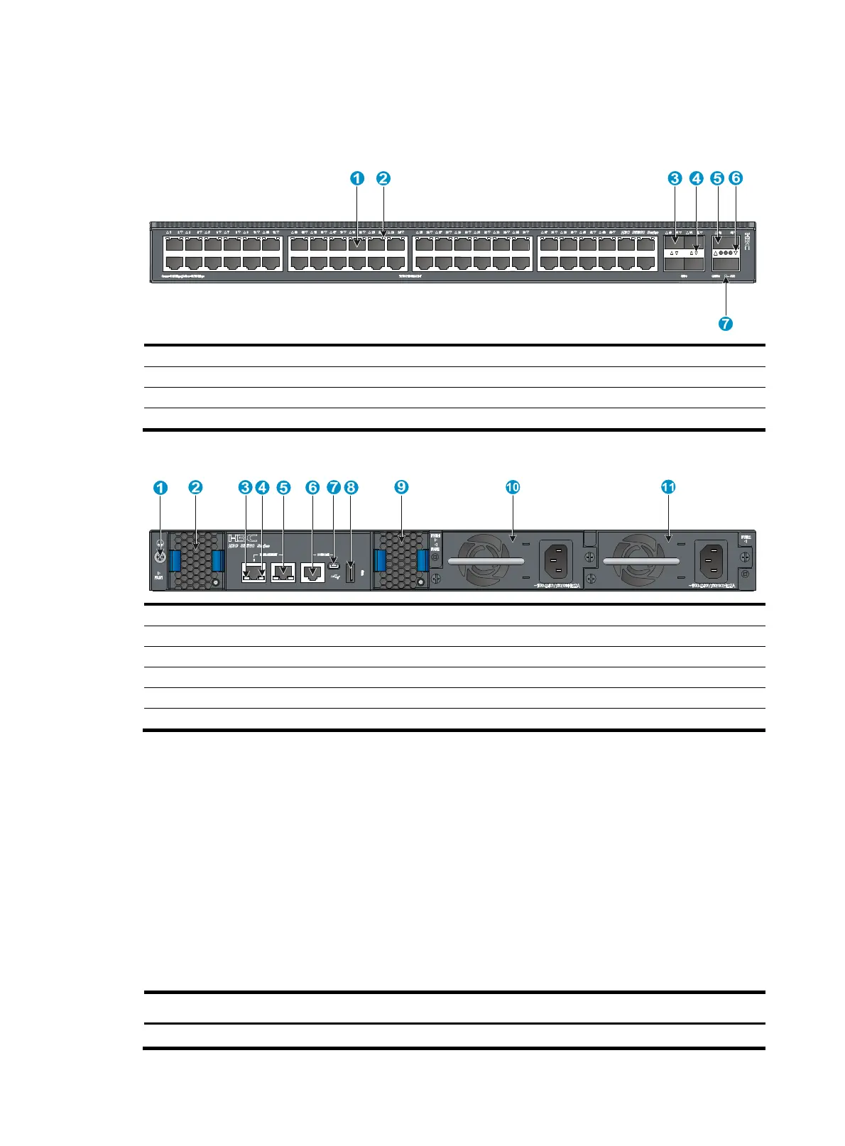
Figure 78 S5560-54QS-EI front panel
(1) 10/100/1000BASE-T autosensin
Ethernet port
(2) 10/100/1000BASE-T
autosensin
Ethernet port LED
(3) SFP+ port (4) SFP+ port LED
(5) QSFP+ port (6) QSFP+ port LED
(7) System status LED (SYS)
Figure 79 S5560-54QS-EI rear panel
(1) Grounding screw (2) Fan tray 1
(3)
CT LED for the mana
ement Ethernet port
(4) LINK LED for the mana
ement Ethernet port
(5) Mana
ement Ethernet port (6) Console port
(CONSOLE)
(7) Mini USB console port (8) USB port
(9) Fan tray 2 (10) Power module 1
(11) Power module 2
The S5560-54QS-EI switch comes with power module slot 1 empty and power module slot 2 installed
with a filler panel. You can install one or two power modules for the switch as required. In this figure,
two PSR150-A1 AC power modules are installed in the power module slots. For more information about
installing and removing a power module, see "Installing/removing a power module."
T
he S5560-54QS-EI switch comes with the two fan tray slots empty. You must install two fan trays of the
same model for the switch. In this figure, two LSPM1FANSA fan trays are installed in the fan tray slots. For
more information about installing and removing a fan tray, see "Installing/removing a fan tray."
Technical specifications
Table 10 Technical specifications for non-PoE switch models (1)
Item S5560-30S-EI S5560-54S-EI S5560-30F-EI S5560-30C-EI
Dimensions (H 43.6 × 440 × 260 43.6 × 440 × 260 43.6 × 440 × 360 mm 43.6 × 440 × 360

 Loading...


