89
Appendix D Cooling system
To dissipate heat timely and ensure system stability, the switch uses high-performance cooling system.
Consider the site ventilation design when you plan the installation site for the switch.
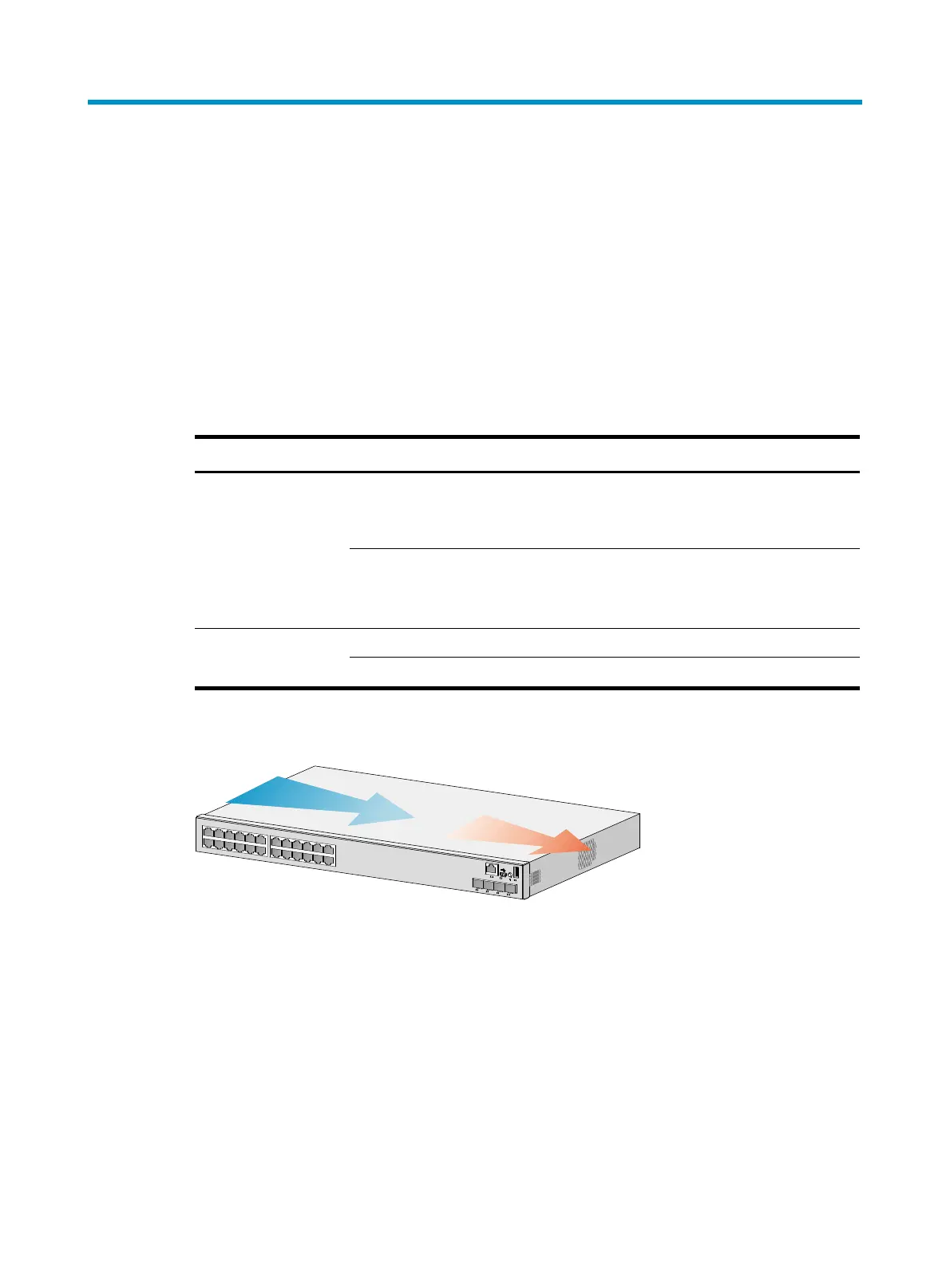
• The S5560-30S-EI and S5560-54S-EI switches use fixed fan trays. Ambient air flows in through the
left side panel and exhausts through the right side panel.
• The S5560-E1 switches, excluding the S5560-30S-EI and S5560-54S-EI switches, use
hot-swappable fan trays. You can provide airflow from the power module side to the port side or
from the port side to the power module side for the switch by using different fan trays. For heat
dissipation, install two fan trays of the same model for the switch.
Table 40 Cooling system for the S5560-E1 switches (excluding S5560-30S-EI and S5560-54S-EI)
Switch model Available fan tray Airflow direction
S5560-30C-EI
S5560-30C-PWR-EI
S5560-30F-EI
S5560-34C-EI
S5560-54C-EI
S5560-54C-PWR-EI
LSPM1FANSA
From the power module side to the port side and two
sides of the chassis
LSPM1FANSB
From the port side and two sides of the chassis to the
power module side
S5560-54QS-EI
LSPM1FANSA From the power module side to the port side
LSPM1FANSB From the port side to the power module side
Figure 83 Airflow through the S5560-30S-EI switch (with fixed fan trays)

 Loading...


