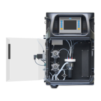
Component Description
Peristaltic pump(s) Sets the pump to on and off to examine the operation. If there is no flow, examine if there is
a blockage in the pump tubing between the two pump halves. Keep the drain pump set to
on during the test to let fluids drain.
Micropump(s) Sets the micropump to on and off to examine the operation. If the micropump does not
operate during the start-up, there may be a blockage in the micropump duckbill (e.g.,
caused by calcium carbonate). Carefully flush the micropump with a syringe filled with
demineralized water while the micropump is active. Enter a number of pulses and push
Pulse. If the blockage continues and the micropump does not activate, replace the
micropump duckbills. Refer to Replace the micropump duckbills on page 32.
Dispenser(s) Examine the dispensers operation with the empty and filling button. If the Emergency stop
button was pushed, startup the dispensers with the INIT button.
Drain/Level pinch
valve(s)
Sets the pinch valve and drain pump to on and off to examine the operation. When the
pinch valve is set to off and the drain pump is set to on, the analysis vessel is drained.
When the pinch valve and the drain pump are set to on, the level procedure is done. If the
component is not operating correctly, make sure that the tubing is not clogged or there is a
blockage. Examine the tube position in the pinch valve. The tubing in the rear side is for
level procedure. The tubing in the front is for drain procedure.
Stirrer Sets the stirrer to on and off to examine the operation.
Colorimetric
sensor
Do the steps that follow to examine the operation:
1. Fill the analysis vessel with water.
2. Set the voltage of the sensor output to 9.5 V.
3. Do a calibration.
4. Absorbance output value is ~0 mAU.
5. Drain the analysis vessel.
6. Absorbance output value is approximately 300 mAU.
If there is no difference in the result values, the photometer operation is not correct.
Titrimetric and ion-
selective analyzer
unit
Do the steps that follow to examine the operation:
1. Do a calibration.
2. Drain the analysis vessel.
Stream selection
valve(s)
Sets the stream selection valve to on and off to examine the operation.
7.2 Do an input/output signal test
Do a test on the analyzer inputs/outputs before the unit is put into operation.
1. On the analyzer display, push F2 > RIGHT arrow.
A list with all of the installed components shows. Refer to Figure 9.
24
English

 Loading...