22
Operating Manual
POWER CLAMP
English
Quality Wins.
© 2021/09 Haimer POWER CLAMP
Start-up
The POWER CLAMP is almost completely preassembled.
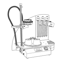
Only the linear guide (6) needs to be bolted to the housing
and aligned suitably.
Important: For safety reasons there must be a con-
ductive contact between the linear guide and the
housing. For that reason the linear guide must be
installed very carefully.
• Remove the screws (50) and the locking washers (51).
The stop clamp (43) remains in its position.
• Set the linear guide (6) on the stop clamp (43) (Comfort
version: There is no stop clamp here. The linear guide
is set directly on the baseplate).
• Thread the bolts (50) in and turn them so that there is
still some play.
Safety note: The four locking washers (51) must
be directly underneath the screw head.
• Insert the spring tensioner (10) into the socket under
the baseplate.
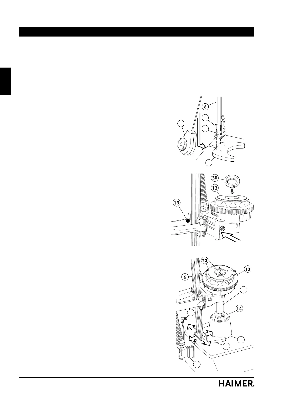
• Pull the locking bolt (19) and place the coil (13) in the
holder of the linear guide. Ensure that the locking bolts
(19) are properly seated.
• Two ferrite screening disks (30) are supplied with the
inductor. Place the standard disk with the large hole
in the inductor (13) and lock it into position by turning
it clockwise.
• Place the chuck holder (42) on the baseplate and push
it up against the stop clamp (43) beside the linear guide
(6). The chuck holder (42) must be up against the stop
clamp (not applicable in the Comfort version).
• Now place a chuck support (14) in the chuck holder
(42). Comfort version: Place the chuck support (14) in
the turntable.
• Place a suitable shrink-fit chuck (52) in the chuck sup-
port (14).
• Adjustable coil, NG version:
Place the coil with the rotary disk (23) on the diameter
of the chuck.
Coil with stop disks: Place a stop disk (49) in the coil
(13). The stop disk must match the diameter of the
selected shrink fit chuck.
Turn the stop disk clockwise until it audibly clicks into
place (bayonet-type connection).
• Slowly lower the coil (13) until it rests on the chuck (52).
43
4
42
52
32