25
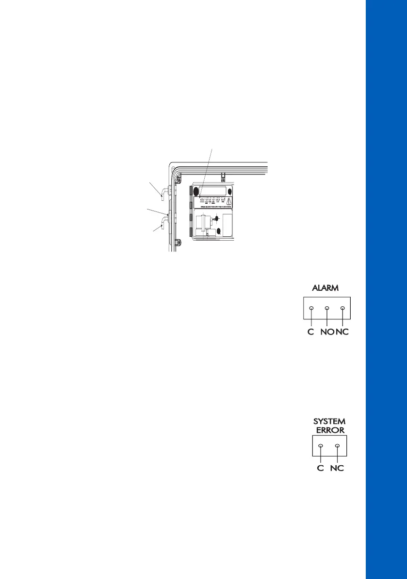
WARNING! DISCONNECT POWER SUPPLYPRIOR TO
REMOVAL OF THIS COVER.
Cable access for
All alarms“ONLY”
Watertight Grommet
and Nut Assembly
Cable access for
RS232 and Recorder
Output Connections
“ONLY”
Recorder Output and Relay Access
Hard wiring for alarms and relays recorder output and serial communication can be accomplished
through four watertight connectors on the left side of the enclosure, by passing wires through the
rubber grommet and tightening the nut as described earlier.
Refer to the drawings for proper wire connections.
INITIAL PREPARATION AND INSTALLATION
Alarm Relay
A system alarm feature provides relay activation to signal that the measuring
value exceed the alarm setpoints. The alarm relay is closed (Common connect to
Normal Close) if the value is lower than alarm low setpoint or higher than alarm
high setpoint.
The ALARM LED blinks when alarm is active.
Note: The Alarm relay is power-fail safe and is closed when the analyzer is not powered.
System Error Relay
A system error feature provides relay activation to signal the need for operator
intervention through an external device, such as a buzzer, a light or any other
electrical equipment. When errors appears, the relay is closed (Common connect to
Normal Close).
The SYSTEM ERROR LED blinks when a system error occurred.