MARK IV HD J2 TAMPER OPERATION PAGE 2.2 - 9
BULLETIN 5082505 JUPITER II REVISED 10 - 2020
2.2
2.2.1 Jupiter II Control System
2.2.1.7 Jupiter System Description
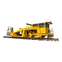
1. The JAM contains a microprocessor that is responsible for
distributing programming information to the other Jupiter modules on
the machine. Specific software for the machine is loaded into the
JAM at the factory. The software can be updated in the field by
connecting a memory device that contains the new software to one
of the USB connections or by installing a different internal memory
flash card.
2. All Jupiter controlled functions are displayed on the touch screen monitor and are
controlled by the Jupiter computer, either manually or automatically.
3. The Jupiter Network Modules are located at various positions on the machine, in close
proximity to the components that they control or monitor. The types of modules used on
the machine are briefly described following:
4. Analog Module: This module is used with analog input devices that
have a varying feed-back voltage; such as engine sensors, fuel
gauge, position sensors, etc.
5. Digital Module: This module is used with digital input devices that
when actuated send the power back to the module; such as limit
switches, pressure switches, etc. or used with digital output devices
that have two positions (On / Off); such as valve coils, relays, lights,
alarms, etc. This module can also be used to control proportional output signal devices
that are Pulse Width Modulation (PWM) capable; such as proportional valves, etc.
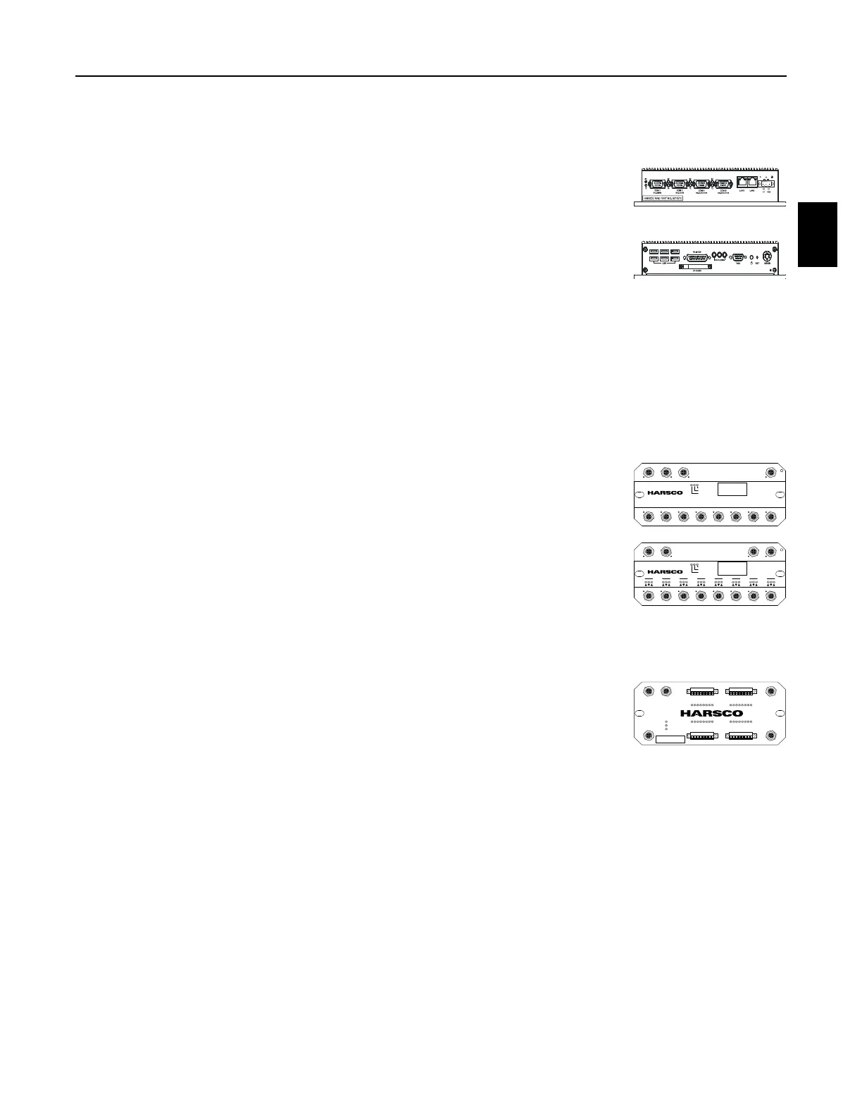
6. High Density Digital Module: This module is used with digital input
devices that when actuated send the power back to the module such
as; limit switches, pressure switches, etc. or used with digital output
devices that have two positions (On / Off) with low voltage items
such as; relays, lights, alarms, etc. Outputs are one amp max per channel (8 amps max for
the module with one field power cable connected or 16 amps max for the module with two
field power cables connected). This module is used when there is a high volume of digital
devices in an area that are being controlled or monitored.
a. The High Density Digital Module interfaces with machine components in much the
same way as the standard Digital Module.
b. One major difference is the High Density Digital Module offers 32 channels which can
be either input or output channels depending on the software programming while the
standard Digital Module has 16 input channels and 8 output channels.
c. The other major difference is how the wires are connected to the High Density Digital
Module. The standard Digital Module has eight 5 pin M12 connectors while the High
Density Digital Module has 32 connectors where wires can be connected directly.
CAN 1 in CAN 1 out Field Power
C1 C2 C3 C4 C5 C6 C7 C8
CAN 2
Download
Run
Error
4019453 Rev A www.har sco.com
Analog Input Mod ule
746911
Supply Voltage DC 9 - 30V
Software - Version 1.00
Serial Number 86 0922LUT00001
CAN 1 in CAN 1 out Field Power
C1
124
C2
124
C3
124
C4
124
C5
124
C6
124
C7
124
C8
124
Download
Run
Error
4019452 Rev A www.harsco.com
Digita l Input / O utput Mo dule
746910
Supply Voltage DC 9 - 30V
Software - Version 1.00
Serial Number 86 0921LUT00015
CAN 1
IN
FIELD POWER 1
OUT
HDIO Digital Input / Output Mo dule
PN: 4028741 Rev: 00
SN: AC2010-00004
DOWNLOAD
RUN
ERROR
CAN 2 FIELD POWER 2
C1
12345678
C2
12345678
C3
12345678
C4
12345678
 Loading...