PAGE 1 - 12 SAFETY / GENERAL MARK IV HD J2 TAMPER
REVISED 10 - 2020 INFORMATION BULLETIN 5082505
1
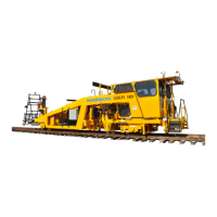
1.4 Description
The Mark IV Tamper is used for production and switch tamping, and transit system work. The
Hydraulic Drive (HD) model incorporates a direct drive two speed gearbox on both the front and
rear axles that provide full time four wheel drive in either the Travel or Work Mode.
The machine is equipped with Jupiter II control system and System V software. Ergonomic
operator control is provided through arm panel keypads, joysticks, a USB keyboard and a 17
inch touch screen color monitor used as the graphical interface.
The Jupiter II (J2) Control System utilizes a Control Area Network (CAN) communications
scheme to read and control Input / Output (I/O) modules distributed remotely around the
machine. These modules are placed strategically to be in close proximity to the devices with
which they interact.
The advanced System V control system delivers accurate, repeatable results and effective
operator interface for computer controlled automatic ramping, super-elevation, zeroing of
references, and continuous cross level monitoring.
The four heavy-duty vibrator assemblies are powered by hydraulic motors designed to allow
one workhead to tamp one rail independently of the other. Tamping of unevenly spaced or
skewed ties is simplified by manually adjustable tamping tool position. Tamping tools for
individual workheads can be positioned closer together (squeezed in) prior to the work cycle,
allowing insertion in areas of tight tie spacing. Workhead depth can be varied from within the
cab using operator-defined settings on the pop-out workhead panel. This panel also displays
the current workhead position along with the upper position (standby) and the lower position
(squeeze) for each workhead. This increases productivity by automatically returning the
workheads to a lower standby position when indexing during production runs (Production
Mode), and to a higher position when moving workheads through a switch or turnout (Switch
Mode).
A fully enclosed, sound suppressed and insulated cab is mounted on rubber isolators that is
accessible from either side of the machine via a rear platform equipped with conventional stair
type steps. The rubber isolators provide an excellent ride comfort for the operator and added
protection for electronic components. The operator has an unobstructed view of the work area
and all machine operation, and safety lock controls are within comfortable reach. Front and rear
wipers and a dual tone air horn are included.
1.5 Orientation - See Figures 1-1 and 1-2
Front / rear and left / right are determined from the operator's seat in the cab. The lining /
surfacing buggy is located on the front of the machine and the cab / operator's seat is located
on the rear of the machine. The jacking / tamping components are located on both the left and
right sides of the machine.
 Loading...