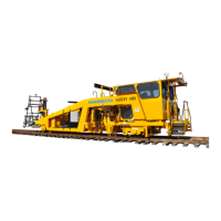
PAGE 2.1 - 16 OPERATION MARK IV HD J2 TAMPER
REVISED 10 - 2020 CONTROLS BULLETIN 5082505
2.1
2.1.2 Controls - Exterior
(19) Power Distribution Box (PDB) - See Figure 2.1-11
The Power Distribution Box (PDB) is located on the left side of the machine behind of the
engine. The Power Distribution Box houses the electrical components (fuses, terminal blocks,
relays, circuit breakers, etc.) for the electrical system of the machine.
(20) Emergency Pump - See Figure 2.1-12
(21) Emergency Pump Switch - See Figure 2.1-12
The Emergency Pump and Switch are located on the right side of the machine next to the
hydraulic reservoir. The emergency pump can be used to raise and lock hydraulic components
in the Travel position, should the engine and/or hydraulic pumps become inoperable.
a. Push in and hold the switch to build up hydraulic pressure. At the same time, move
the applicable component control (switch, valve, etc.) to move the component to the
desired position. When the component is in the desired position, release the switch.
b. Important: DO NOT operate the emergency pump for an extended period of time, as
the pump could over-heat and be damaged.
(22) Shadowboard Lock Valve - See Figure 2.1-13
(23) Shadowboard Lift Valve - See Figure 2.1-13
The Shadowboard Lock and Lift Valves are located on the right side of the machine above the
combo clamp.
a. Move the lock valve down to unlock the shadowboard. Move the lock valve up to lock
the shadowboard.
b. Pull out the lift valve to lower the shadowboard bias wheels to the Work position.
Push in the lift valve to raise the shadowboard bias wheels to the Travel position.
(24) Receiver Buggy Lock Valve - See Figure 2.1-14
(25) Receiver Buggy Lift Valve - See Figure 2.1-14
The Receiver Buggy Lock and Lift Valves are located on the right side of the machine behind of
the right rear wheel.
a. Pull out the lock valve to unlock the receiver buggy. Push in the lock valve to lock the
receiver buggy.
b. Move the lift valve down to lower the receiver buggy bias wheels down to the Work
Position. Move the lift valve up to raise the receiver buggy bias wheels up to the
Travel position.
 Loading...