PAGE 2.1 - 62 OPERATION MARK IV HD J2 TAMPER
REVISED 10 - 2020 CONTROLS BULLETIN 5082505
2.1
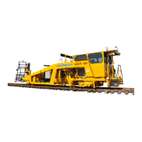
2.1.14 Callisto Geo System Option - See Figures 2.1-45, 2.1-46 and 2.1-47
The Callisto Track Geometry system provides precise and accurate inertial based track
geometry data for use with tampers. Built on an inertial measurement unit containing a GPS
receiver, along with an industrial laser / camera based gauge measurement system, industry
standard track geometry channels are generated and communicated to the tamper. This allows
for high speed pre-recording without requiring deployment of the traditional geometry buggies.
With operational speeds exceeding 25 miles per hour (40 kilometers per hour), tamper
productivity and quality can be increased. The system consists of the following components:
(1) Callisto GPS Box: Located on the front face of the rear derail bar below the cab.
(2) Key Switch: Located inside the cab near the left control panel.
(3) Laser Cutoff Switches: Located on the left and right rear sides of the machine.
(4) Red Indicators: ON when the lasers are turned ON.
(5) Green Indicators: ON when the lasers are turned OFF.
(6) Laser Units / Shields: Located on the left and right rear sides of the machine. The
shields help prevent any unwanted sunlight from refracting off the rail or any other rail
bound metallic surface.
(7) GPS Antenna: Located on the top of the cab roof.
1. Important: See the Operation Manual and Installation Guide supplied with the Callisto
Geo System for operating information.
2. Pull out both the left and right Laser Cutoff Switches (3) to the ON position so the Laser
Units (5) will turn ON when the Callisto Geo System is turned ON.
3. Rotate the key in the Key Switch Box (2) to the ON position to turn ON the Callisto Geo
Box (1), Laser Units (6) and GPS Antenna (7). The Red Indicators (4) will illuminate in the
Key Switch Box (2) and in both the left and right Laser Cutoff Switch Boxes (3).
4. When finished using the Callisto Geo System, rotate the Key Switch (2) to the OFF
position to turn OFF the Callisto Geo Box (1). The Green Indicators (5) will illuminate in the
Key Switch Box (2) and in both the left and right Laser Cutoff Switch Boxes (3).
5. Push in both the left and right Laser Cutoff Switches (3) to the OFF position to shut OFF
Laser Units (6).
 Loading...