Electrical connections PMX
98 A4354-2.2 HBM: public PMX
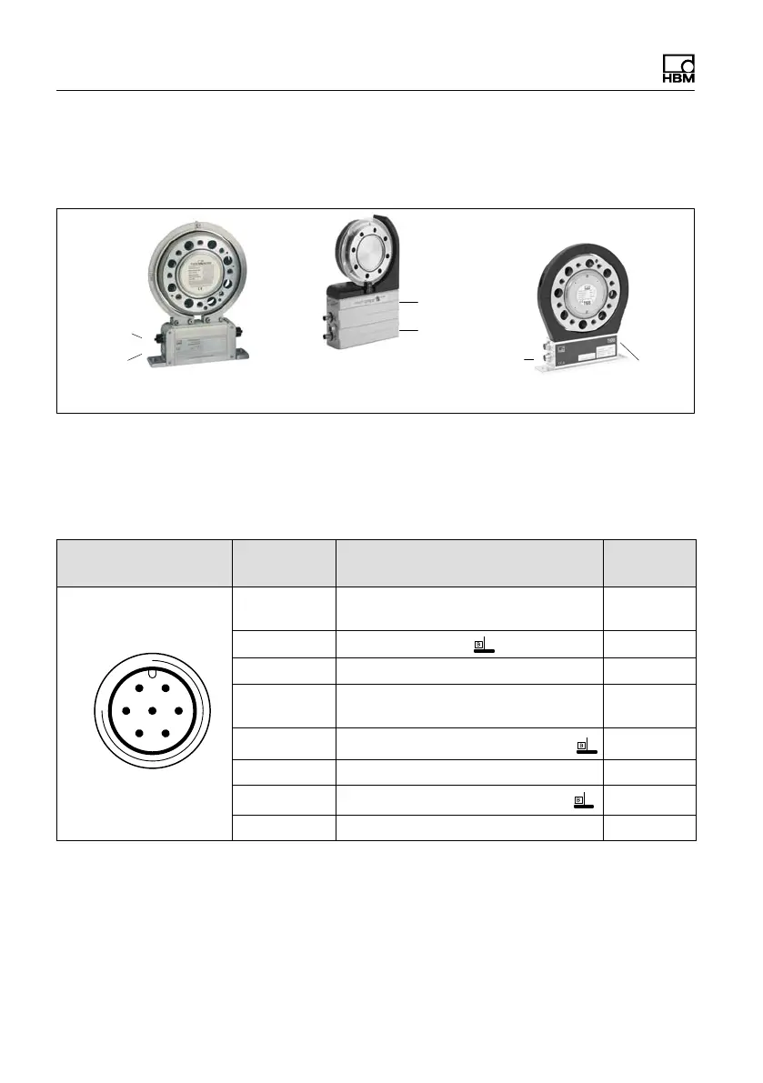
8.4.4.9 Connection and configuration of the HBM
torque flange (T10, T12, T40)
Connector 1
Connector 2
Connector 1
Connector 2
T10 T12
Connector 1
Connector 2
Connector 1: 1-KAB153-6 (torque)
Connector 2: 1-KAB154-6 (speed); 1-KAB164-6 (speed, angle)
T40
Fig. 8.21 Connector positions T10, T12, T40
Assignment for connector 1: T10, T12, T40
Supply voltage and frequency output signal.
Device connector Connector
pin
Assignment0V Wire color
6
1
5
7
2
4
3
Top view
1 Torque measurement signal
(frequency output; 5 V
1),2)
)
wh
2 Supply voltage 0 V; bk
3 Supply voltage 18 V 30 V bu
4 Torque measurement signal
(frequency output; 5 V
1),2)
)
rd
5 Measurement signal 0V, symmetric gy
6 Shunt signal trigger 5 V 30 V gn
7
Shunt signal
gy
Shielding connected to housing ground
1)
RS-422 complementary signals; with cable lengths exceeding 10 m, we
recommend using a termination resistor R = 120 ohms between the (wh) and (rd) wires.
2)
RS 422: Pin 1 corresponds to A, Pin 4 corresponds to B.

 Loading...