Home
HBM
Measuring Instruments
T10F
HBM T10F User Manual
4
of 1
of 1 rating
84 pages
Give review
Manual
Specs
To Next Page
To Next Page
To Previous Page
To Previous Page
Loading...
Mechanical installation
T10F
A0608-14.0
HBM:
public
21
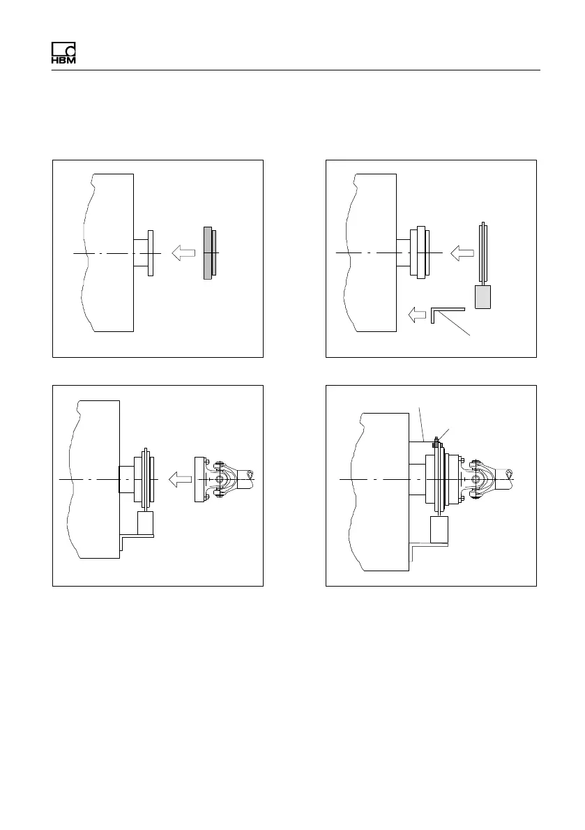
6.3.1
Installation
without dismantling the antenna
ring
1. Install rotor
2. Install stator
3. Finish installation of shaft train
Customer
mounting
Support supplied by customer
Clamp fixture
4. Mount the clamp fixture where required
20
22
Table of Contents
Table of Contents
3
Safety Instructions
6
Markings Used
11
The Markings Used in this Document
11
Symbols on the Product
12
Torque Flange Versions
13
Application
14
Structure and Mode of Operation
15
Mechanical Installation
17
Conditions on Site
19
Installation Orientation
19
Installation Options
20
Installation Without Dismantling the Antenna Ring
21
Installation with Subsequent Stator Mounting
22
Installation Example with Couplings
23
Installation Example with Joint Shaft
23
Mounting the Rotor
24
Mounting the Stator
28
Installing the Clamp Fixture
31
Fitting the Slotted Disc (Speed Measuring System)
33
Aligning the Stator (Speed Measuring System)
34
Electrical Connection
37
General Information
37
FCC and IC Compliant Installation for US and Canada Installation Only
38
Shielding Design
39
Option 2, Code KF1
41
Adaptation to the Cable Length
41
Option 2, Code SF1/SU2
43
Supply Voltage
46
Calibration
48
Calibration Option 2, Code KF1
49
Calibration Option 2, Code SF1/SU2
49
Settings
50
Torque Output Signal, Code KF1
51
Torque Output Signal, Code SF1/SU2
51
Setting up the Zero Point
51
Functional Testing
52
Power Transmission
52
Aligning the Speed Module
53
Setting the Pulse Count
55
Vibration Suppression (Hysteresis)
56
Form of Speed Output Signal
56
Type of Speed Output Signal
58
Loading Capacity
59
Measuring Dynamic Torque
59
Maintenance
61
Speed Module Maintenance
61
Dimensions
62
Rotor Dimensions
62
Stator Dimensions
64
Mounting Dimensions
66
Order Numbers, Accessories
68
Specifications
70
Output MD Torque (Connector 1)
78
Output Signals
78
Supplementary Technical Information
78
Output N: Speed (Connector 2)
79
Connector 2, Double Frequency, Stat. Direction of Rotation Signal
80
Axial and Radial Run-Out Tolerances
81
Additional Mechanical Data
82
4
Based on 1 rating
Ask a question
Give review
Questions and Answers:
Need help?
Do you have a question about the HBM T10F and is the answer not in the manual?
Ask a question
HBM T10F Specifications
General
Brand
HBM
Model
T10F
Category
Measuring Instruments
Language
English
Related product manuals
HBM T10FS
112 pages
HBM DMP41
112 pages
HBM K-LK1/600N-WH
40 pages
HBM Spider8
132 pages
HBM ME250 S6
36 pages