Electrical connection
46 A0608-14.0 HBM: public T10F
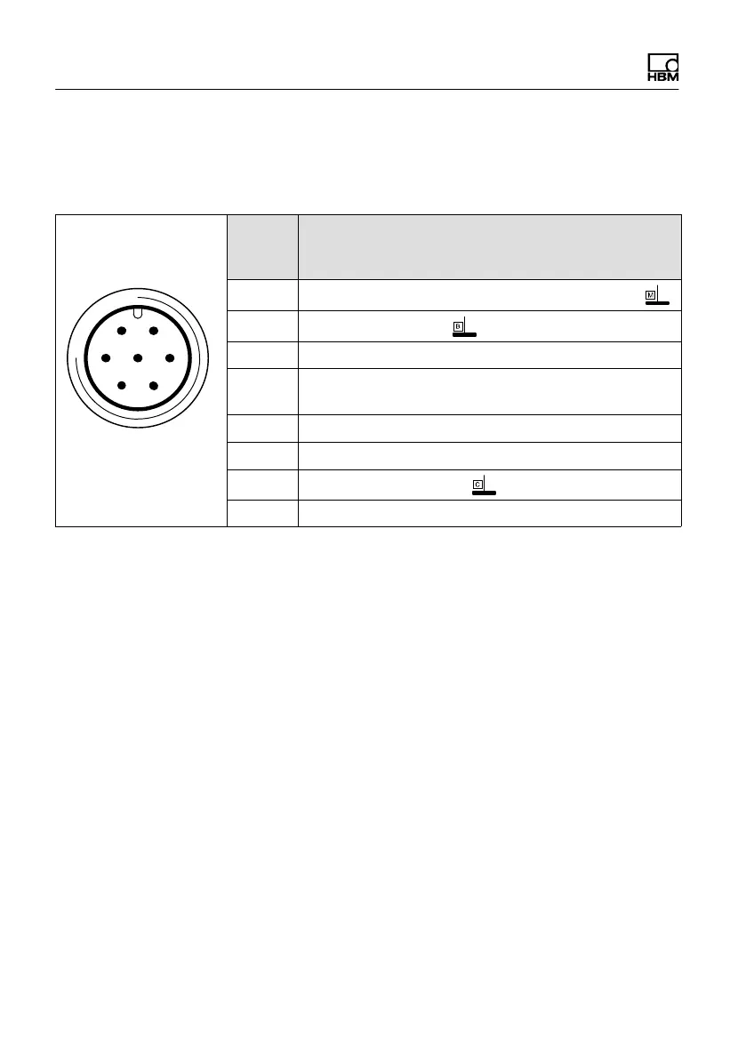
Assignment connector 3
Voltage supply and voltage output signal.
61
5 72
4
3
Binder 723
Top view
Conn.
Binder
Pin
Assignment
1
Torque measurement signal (voltage output; 0 V )
2
Supply voltage 0 V;
3 Supply voltage 18 V ... 30 V DC
4
Torque measurement signal (voltage output;
"10 V)
5 No function
6 Calibration signal trigger 5 V - 30 V
7 Calibration signal 0 V;
Shielding connected to housing ground
7.5 Supply voltage
The transducer must be operated with a separated
extra‐low voltage (18...30 V DC supply voltage), which
usually supplies one or more consumers within a test
bench.
Should the equipment be operated on a DC voltage
network
1)
, additional precautions must be taken to
discharge excess voltages.
The notes in this chapter relate to the standalone
operation of the T10F without HBM system solutions.
1)
Distribution system for electrical energy with greater physical expansion (over several test
benches, for example) that may possibly also supply consumers with high nominal (rated)
currents.