Settings
56 A0608-14.0 HBM: public T10F
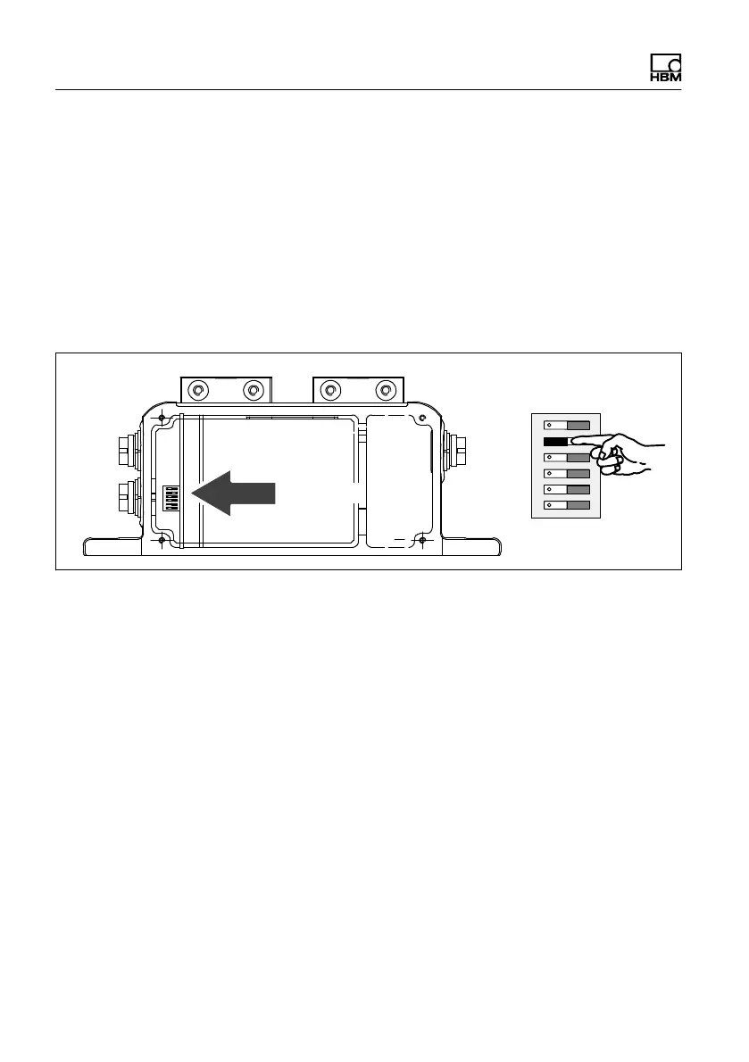
9.6 Vibration suppression (hysteresis)
Low rotation speeds and higher relative vibrations
between the rotor and the stator can cause disturbance
signals that reverse the direction of rotation. Electronic
suppression (hysteresis) to eliminate these disturbances
is connected at the factory. Disturbances caused by the
radial stator vibration amplitude and by the torsional
vibration of the rotor are suppressed.
On Off
S5
Switch S5
Hysteresis
Fig. 9.8 Switch for switching off hysteresis
9.7 Form of speed output signal
In the factory setting, two 90_ phase‐offset speed signals
(5 V symmetrical, complementary RS-422 signals) are
available at the speed output (connector 2). You can
double the pulse count set in each case by moving
switch S6 to the “On" position. Pin 3 then outputs the
direction of rotation as a static direction of rotation signal
(pin 3 = +5 V, pin 7 = 0 V compared to pin 8), if the shaft
turns in the direction of the arrow). At a speed of 0 min
-1
,
the direction of rotation signal has the last measured
value.