Settings
T10F A0608-14.0 HBM: public 51
9.1 Torque output signal, code KF1
The factory setting for the frequency output voltage is 12
V (asymmetrical). The frequency signal is on pin 4
opposite pin 1. It is not possible to change over.
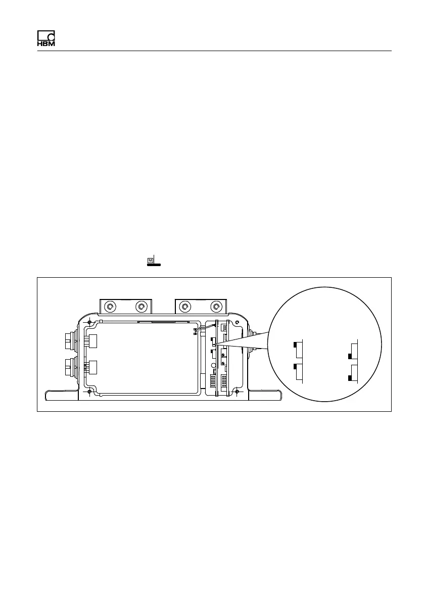
9.2 Torque output signal, code SF1/SU2
The factory setting for the frequency output voltage is 5 V
(symmetrical, complementary RS-422 signals). The
frequency signal is on pin 4 opposite pin 1. You can
change the output voltage to 12 V (asymmetrical). To do
this, change switches S1 and S2 to position 1 (and pin 1
→ ).
12 V
asymmetrical
5 V
symmetrical
Pos.1
Pos.2
S1
S2
Fig. 9.2 Switch for changing the frequency output voltage
9.3 Setting up the zero point
In the case of the torque flange with the voltage output
option (SU2), you can access two potentiometers by
removing the stator cover. You can use the zero point
potentiometer to correct zero point deviations caused by