Electrical connection
T10F A0608-14.0 HBM: public 41
7.3 Option 2, code KF1
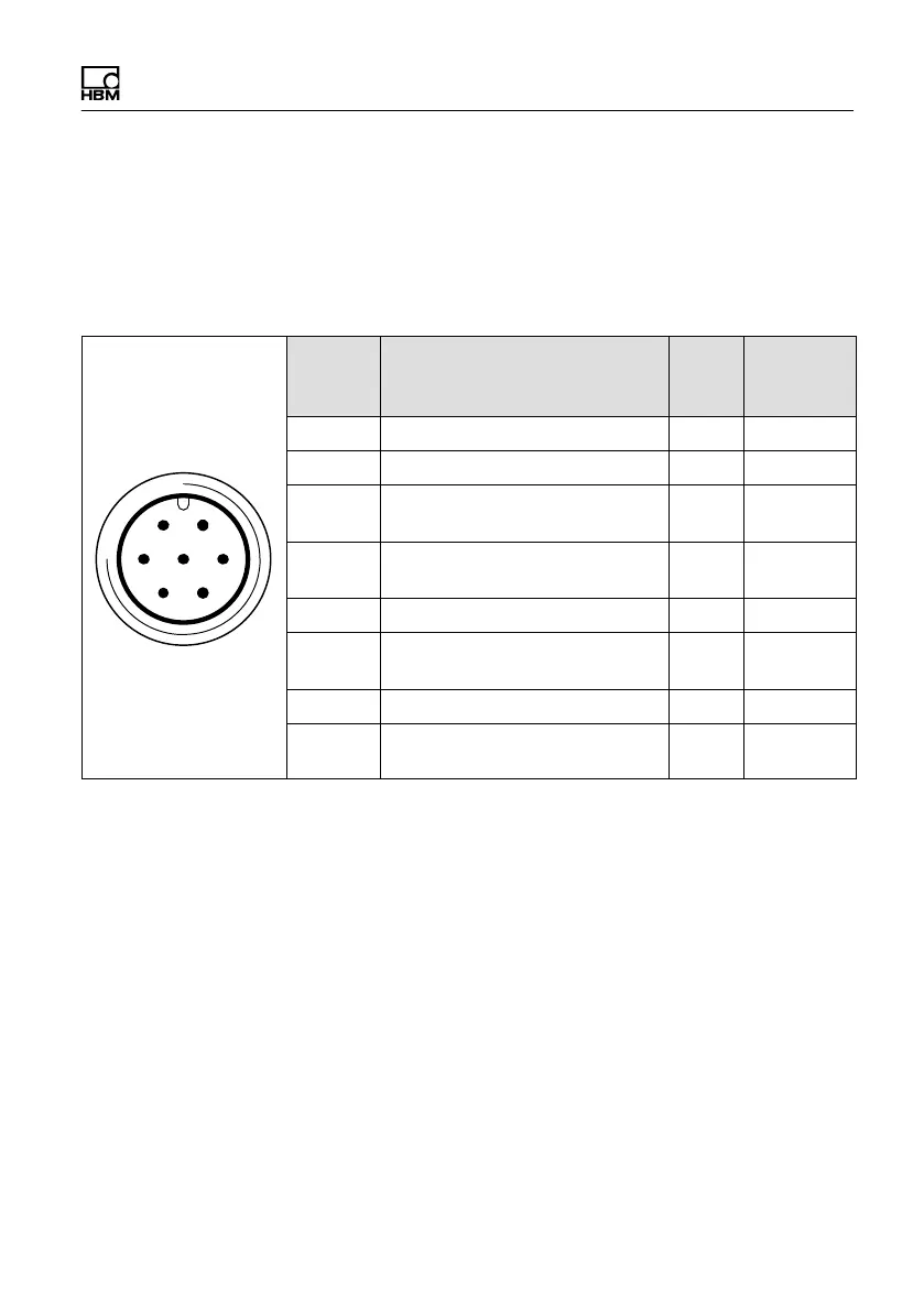
The stator housing has a 7‐pin (Binder 723) device
connector, to which you link the connection cable for
voltage supply and torque signal.
61
5 72
4
3
Binder 723
Top view
Conn.
Binder
Pin
Assignment Wire
color
MS3106
conn.
Pin
1 Supply voltage zero wh A
2 No function bk B
3 Pre‐amplifier supply voltage
(+15 V)
bu C
4 Torque measurement signal
(12 V
PP
; 5...15 kHz)
rd D
5 No function
6 Rotor excitation voltage
(54 V/80 V
PP
; approx.15 kHz)
gn F
7 Rotor excitation voltage (0 V) gy G
Shielding connected to
housing ground
7.3.1 Adaptation to the cable length
The transmission method between the rotor and the
stator determines the function of the torque flange, which
is dependent on:
S the installation situation (for example, covering, area
free of metal parts)
S the length of the cable
S the tolerances of the excitation voltage supply