EasyManuals Logo

HCFA Q Series User Manual

HCFA Q Series
88 pages
To Next Page IconTo Next Page
To Previous Page IconTo Previous Page
Page #22 background imageLoading...
Page #22 background image
20
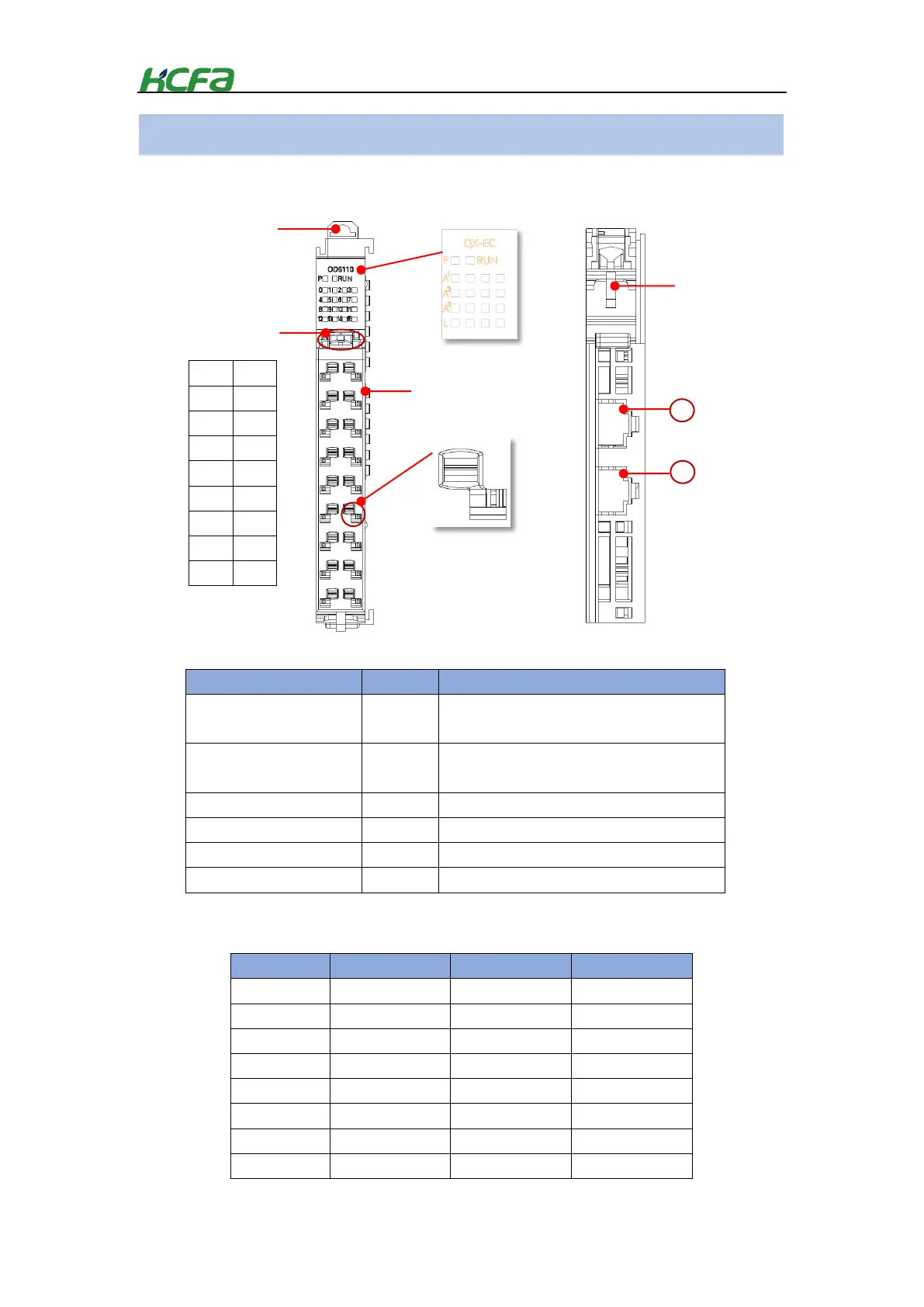
Table 0-6 Indicator description
Symbol
Color
Description
P
Green
The indicator show the current power supply status
of the module.
RUN
Red
EC module running state. Lit means the module is in
normal running state
A1
Red
Channel ACT/LINK indicator of PORT1
A2
Red
Channel ACT indicator of PORT2
A3
Red
Channel ACT/LINK indicator of PORT3
L
Red
Channel LINK indicator of PORT2
24V
24V
0V
0V
FG
FG
NC
NC
NC
NC
NC
NC
NC
NC
NC
NC
NC
NC
Symbol
Description
Symbol
Description
0
24V
9
24V
1
0V
10
0V
2
FG
11
FG
3
Not defined
12
Not defined
4
Not defined
13
Not defined
5
Not defined
14
Not defined
6
Not defined
15
Not defined
7
Not defined
16
Not defined
EC coupler part names and functions
HCQX-EC-D coupler top view
Mounting hook
Connector mounting
hook
Sheetmetal
Terminal block
Indicator
Table 0-7 Channel description
HCQX-EC-D coupler bottom view
1
2
Cable tie
EC coupler channel
description
Port1
EtherCAT IN
Port2
EtherCAT OUT
Port3
QBUS

Table of Contents

Questions and Answers:

Question and Answer IconNeed help?

Do you have a question about the HCFA Q Series and is the answer not in the manual?

HCFA Q Series Specifications

General IconGeneral
BrandHCFA
ModelQ Series
CategoryController
LanguageEnglish