29
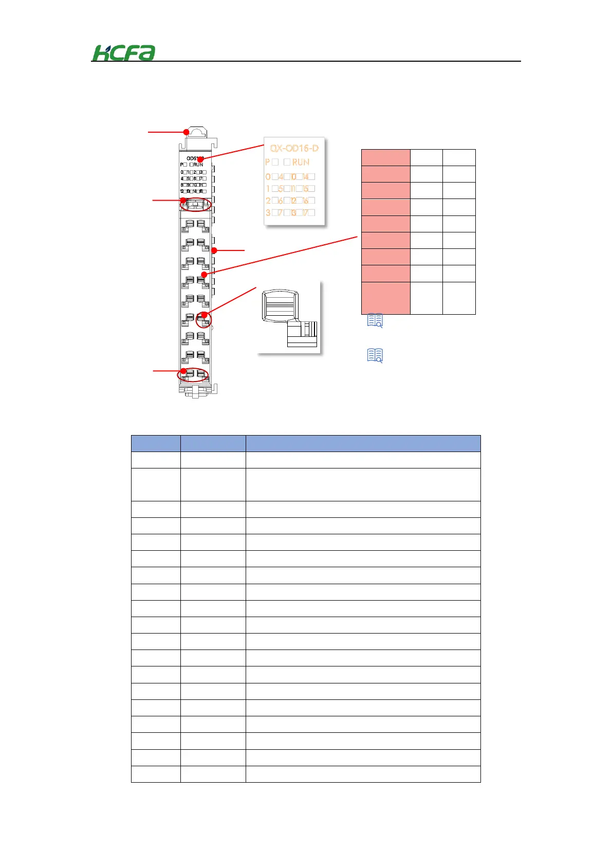
Table 0-13 Digital output module indicator description
The indicator show the current power supply status of the module.
OD module running state. Lit means the module is in normal
running state
Output signal is detected by output channel 0
Output signal is detected by output channel 1
Output signal is detected by output channel 2
Output signal is detected by output channel 3
Output signal is detected by output channel 4
Output signal is detected by output channel 5
Output signal is detected by output channel 6
Output signal is detected by output channel 7
Output signal is detected by output channel 10
Output signal is detected by output channel 11
Output signal is detected by output channel 12
Output signal is detected by output channel 13
Output signal is detected by output channel 14
Output signal is detected by output channel 15
Output signal is detected by output channel 16
Output signal is detected by output channel 17
hook
connection
“Connector installation and wiring”
Output channel arrangements
 Loading...