35
Analog input module terminal arrangements
Table 0-15 Terminal arrangements
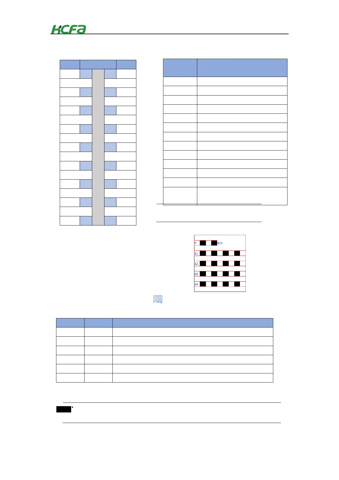
LED indicator arrangements for analog input module
Table 0-16 LED indicator description
Voltage input (negative) of channel 1
Voltage input (positive) of channel 1
Voltage input (negative) of channel 2
Voltage input (positive) of channel 2
Voltage input (negative) of channel 3
Voltage input (positive) of channel 3
Voltage input (negative) of channel 4
Voltage input (positive) of channel 4
Current input of channel 1
Current input of channel 2
Current input of channel 3
Current input of channel 4
AGND(Analog grounding,1、3、5、7、8、
17 internal short-circuited)
For current input, there is no need to
short-circuit V+ and I, only connect I and G.
The indicator shows the current power supply status of the module.
Analog module running state. Lit means the module is in normal running state
Whether ESC channel 1 of analog input module can respond normally.
Whether ESC channel 2 of analog input module can respond normally.
AD operation failure indication
Connection failure indication between AD module and MCU
When the ESC channel in the indicator respond normally, it does not correspond to the specific channel
of analog input.
“2-3-3 EtherCAT slave controller”
 Loading...