39
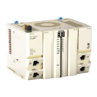
LED indicators arrangements for analog output module
Table 0-18 LED indicator description
The indicator shows the current power supply status of the module.
Analog module running state. Lit means the module is in normal running state
Whether ESC channel 1 of analog output module can respond normally.
Whether ESC channel 2 of analog output module can respond normally.
DA operation failure indication
Connection failure indication between DA module and MCU
When the ESC channel in the indicator respond normally, it does not correspond to the specific
channel of analog output.
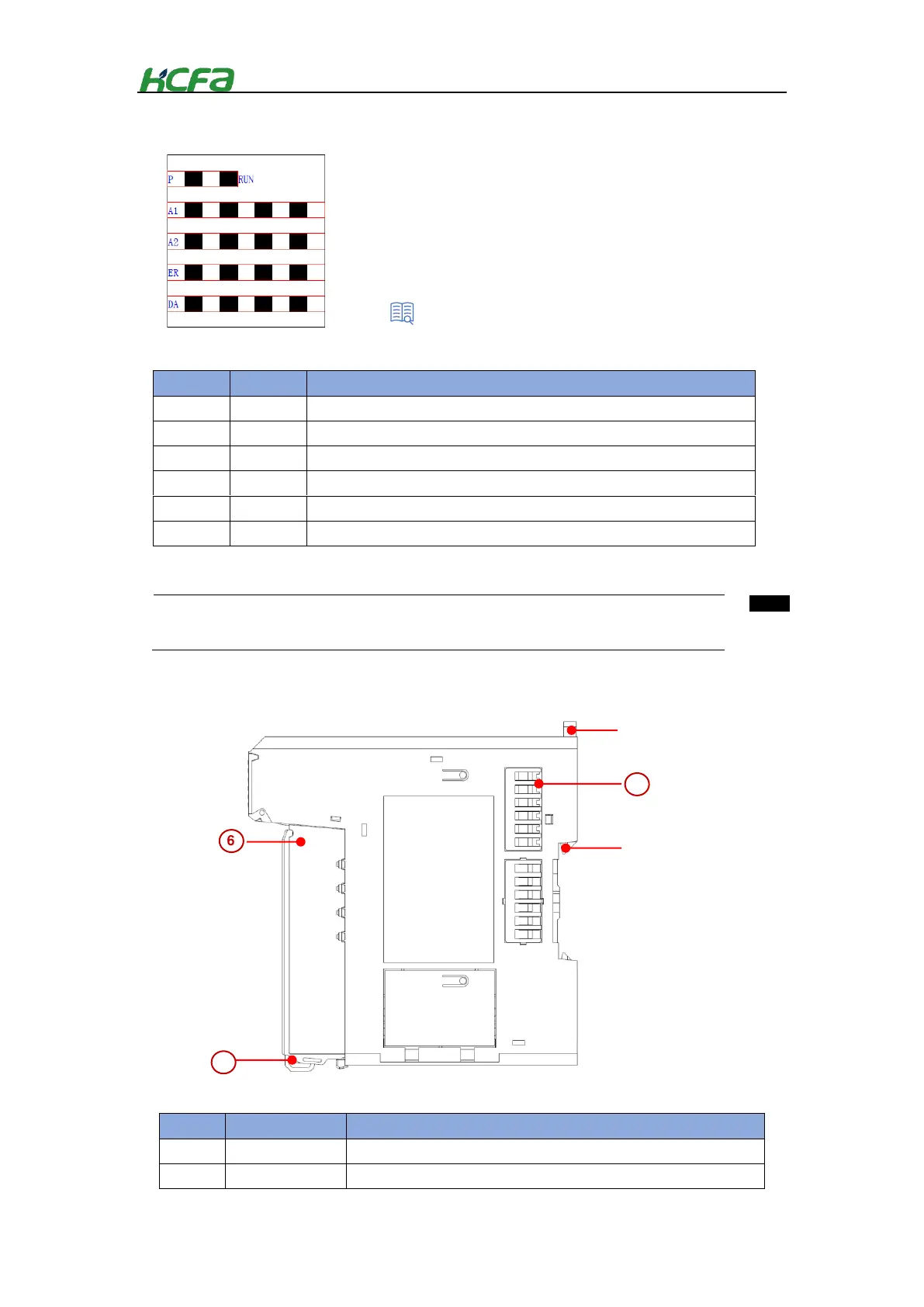
Provide wiring device for easy wiring and module replacement
HCQX-DA04-D viewed from right side
“2-3-3 EtherCAT slave controller”
 Loading...