HEIDENHAIN iTNC 530 213
6.5 Path Contours—Polar Coordinates
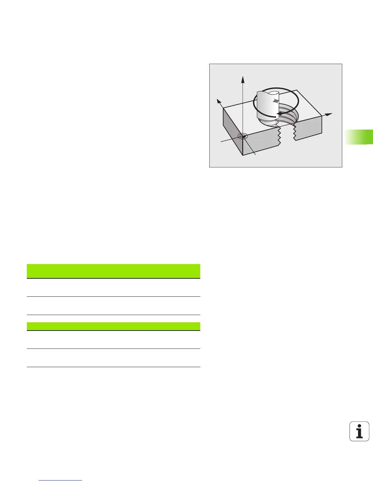
Helical interpolation
A helix is a combination of a circular movement in a main plane and a
linear movement perpendicular to this plane. You program the circular
path in a main plane.
A helix is programmed only in polar coordinates.
Application
Large-diameter internal and external threads
Lubrication grooves
Calculating the helix
To program a helix, you must enter the total angle through which the
tool is to move on the helix in incremental dimensions, and the total
height of the helix.
For calculating a helix that is to be cut in an upward direction, you need
the following data:
Shape of the helix
The table below illustrates in which way the shape of the helix is
determined by the work direction, direction of rotation and radius
compensation.
Thread revolutions n Thread revolutions + thread overrun at
thread beginning and end
Total height h Thread pitch P times thread revolutions n
Incremental total
angle H
Number of revolutions times 360° + angle for
beginning of thread + angle for thread
overrun
Starting coordinate Z Pitch P times (thread revolutions + thread
overrun at start of thread)
Internal thread
Work
direction
Direction of
rotation
Radius
comp.
Right-handed
Left-handed
Z+
Z+
G13
G12
G41
G42
Right-handed
Left-handed
Z–
Z–
G12
G13
G42
G41
External thread
Right-handed
Left-handed
Z+
Z+
G13
G12
G42
G41
Right-handed
Left-handed
Z–
Z–
G12
G13
G41
G42

 Loading...


