392 Programming: Multiple Axis Machining
12.2 The PLANE Function: Tilting the Working Plane (Software Option 1)
Input parameters
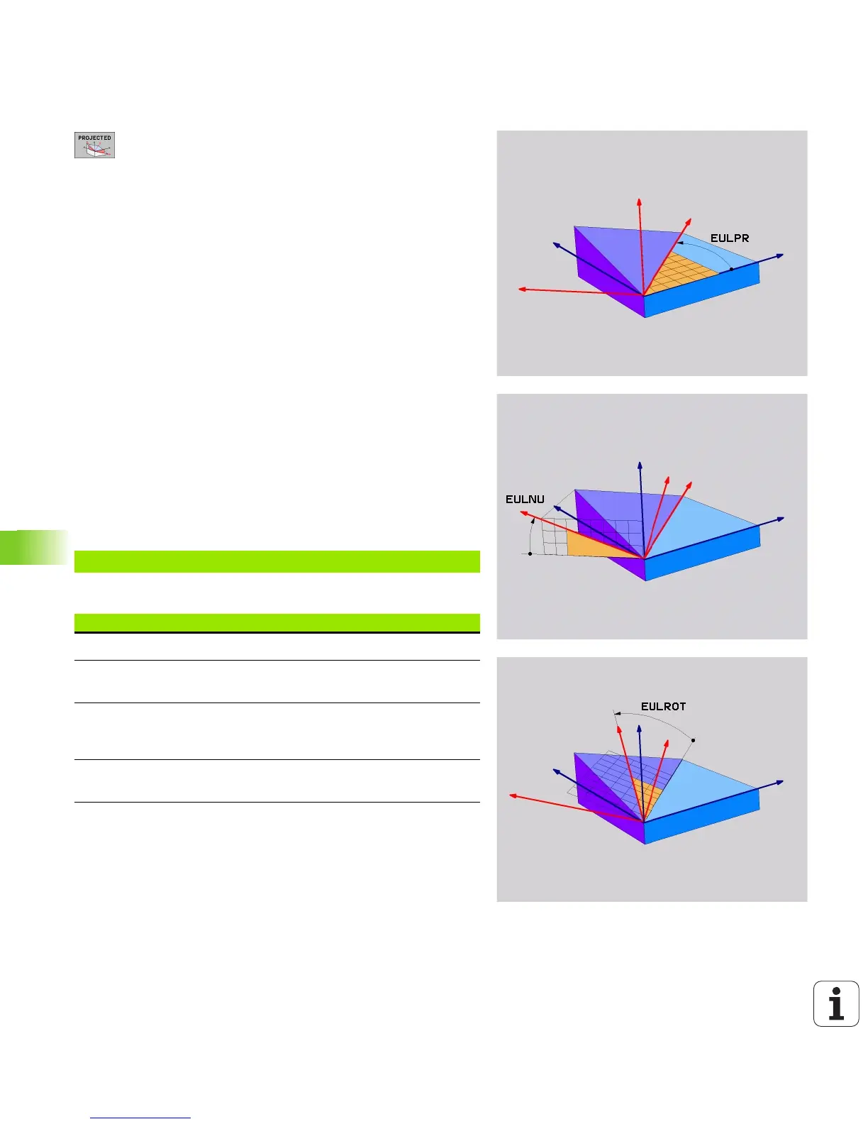
U Rot. angle main coordinate plane?: Rotary angle
EULPR around the Z axis (see figure at top right).
Please note:
Input range: –180.0000° to +180.0000°
The 0° axis is the X axis
U Tilting angle tool axis?: Tilting angle EULNUT of the
coordinate system around the X axis shifted by the
precession angle (see figure at center right). Please
note:
Input range: 0° to +180.0000°
The 0° axis is the Z axis
U ROT angle of the tilted plane?: Rotation EULROT of
the tilted coordinate system around the tilted Z axis
(corresponds to a rotation with Cycle 10 ROTATION).
Use the rotation angle to simply define the direction
of the X axis in the tilted machining plane (see figure
at bottom right). Please note:
Input range: 0° to 360.0000°
The 0° axis is the X axis
U Continue with the positioning properties (see
“Specifying the positioning behavior of the PLANE
function” on page 400)
NC block
Abbreviations used
5 PLANE EULER EULPR45 EULNU20 EULROT22 .....
Abbreviation Meaning
EULER Swiss mathematician who defined these angles
EULPR Precession angle: angle describing the rotation of
the coordinate system around the Z axis
EULNU Nutation angle: angle describing the rotation of
the coordinate system around the X axis shifted
by the precession angle
EULROT Rotation angle: angle describing the rotation of
the tilted machining plane around the tilted Z axis

 Loading...


