HEIDENHAIN iTNC 530 415
12.5 Peripheral milling: 3-D radius compensation with workpiece orientation
12.5 Peripheral milling: 3-D radius
compensation with workpiece
orientation
Function
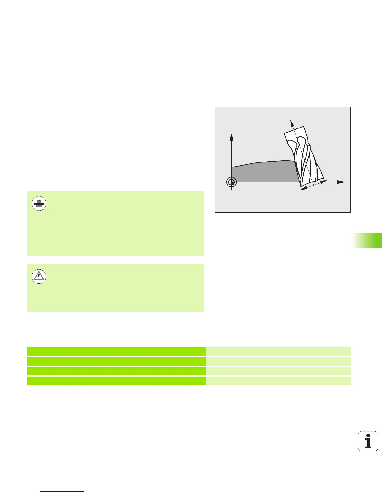
With peripheral milling, the TNC displaces the tool perpendicular to the
direction of movement and perpendicular to the tool direction by the
sum of the delta values DR (tool table and T block). Determine the
compensation direction with radius compensation G41/G42 (see figure
at upper right, traverse direction Y+).
For the TNC to be able to reach the set tool orientation, you need to
activate the function M128 (see “Maintaining the position of the tool tip
when positioning with tilted axes (TCPM): M128 (software option 2)”
on page 410) and subsequently the tool radius compensation. The
TNC then positions the rotary axes automatically so that the tool can
reach the orientation defined by the coordinates of the rotary axes
with the active compensation.
You can define the tool orientation in a G01 block as described below.
Example: Definition of the tool orientation with M128 and the
coordinates of the rotary axes
This function is possible only on machines for which you
can define spatial angles for the tilting axis configuration.
Refer to your machine tool manual.
The TNC is not able to automatically position the rotary
axes on all machines. Refer to your machine manual.
Note that the TNC makes a compensating movement by
the defined delta values. The tool radius R defined in the
tool table has no effect on the compensation.
Danger of collision!
On machines whose rotary axes only allow limited
traverse, sometimes automatic positioning can require
the table to be rotated by 180°. In this case, make sure
that the tool head does not collide with the workpiece or
the clamps.
N10 G00 G90 X-20 Y+0 Z+0 B+0 C+0 *
Pre-position
N20 M128 *
Activate M128
N30 G01 G42 X+0 Y+0 Z+0 B+0 C+0 F1000 *
Activate radius compensation
N40 X+50 Y+0 Z+0 B-30 C+0 *
Position rotary axis (tool orientation)

 Loading...


