446 Manual Operation and Setup
14.2 Moving the Machine Axes
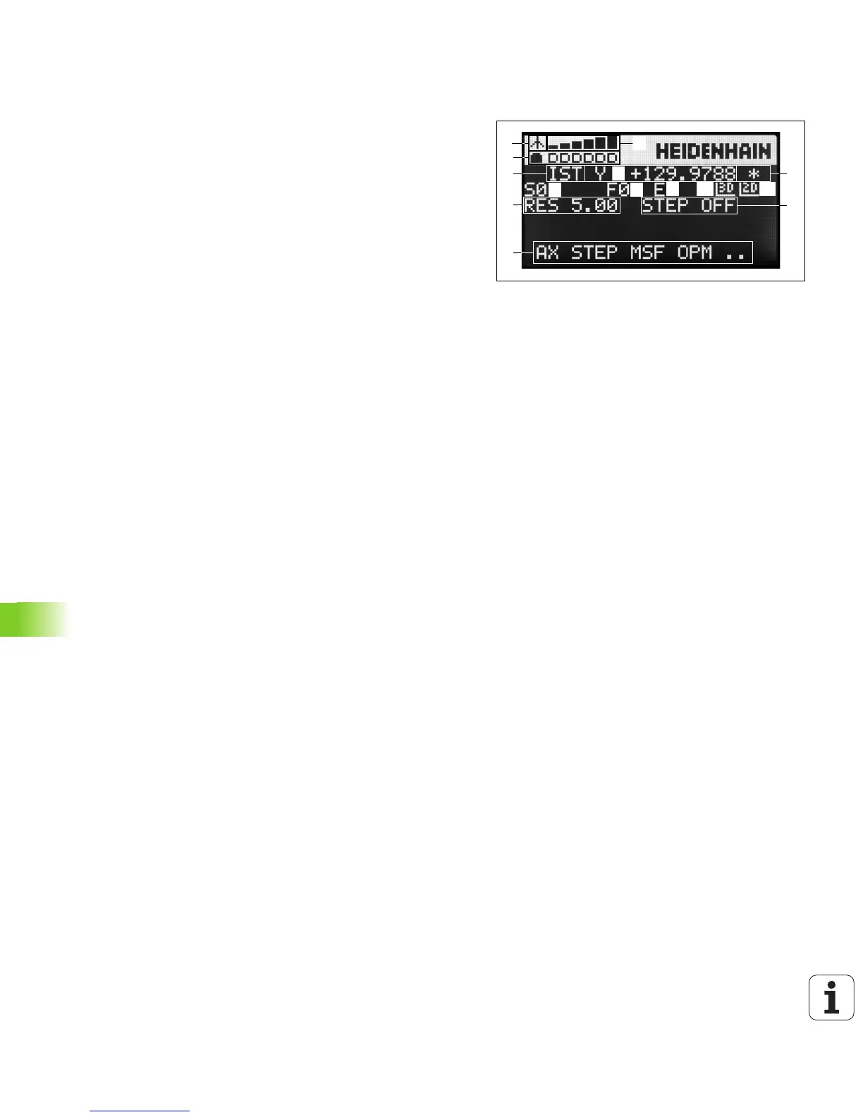
Handwheel display
The handwheel display (see image) consists of a header and 6 status
lines in which the TNC shows the following information:
1 Only HR 550 FS wireless handwheel:
Shows wether the handwheel is in the docking station or
whether wireless operation is active
2 Only HR 550 FS wireless handwheel:
Shows the field strength, 6 bars = maximum field strength
3 Only HR 550 FS wireless handwheel:
Shows the charge status of the rechargeable battery, 6 bars =
fully charged A bar moves from the left to the right during
recharging
4 ACTL: Type of position display
5 Y+129.9788: Position of the selected axis
6 *: STIB (control in operation); program run has been started or
axis is in motion
7 S0:: Current spindle speed
8 F0: Feed rate at which the selected axis is moving
9 E: Error message
10 3D: Tilted-working-plane function is active
11 2D: Basic rotation function is active
12 RES 5.0: Active handwheel resolution. Distance in mm/rev (°/rev
for rotary axes) that the selected axis moves for one handwheel
revolution
13 STEP ON or OFF: Incremental jog active or inactive. If the function
is active, the TNC also displays the active jog increment
14 Soft-key row: Selection of various functions, described in the
following sections

 Loading...


