3.2 Measuring Insulation Resistance
1
2
3
4
5
6
7
8
9
10
11
付録
索引
69
Every time key is pressed, the indi-
cation changes in the order: resistance
current DAR 1 min/15s DAR 1 min/30s
PI resistance current etc.
PI/DAR See 4.2 "Displaying PI and DAR"
(page 83).
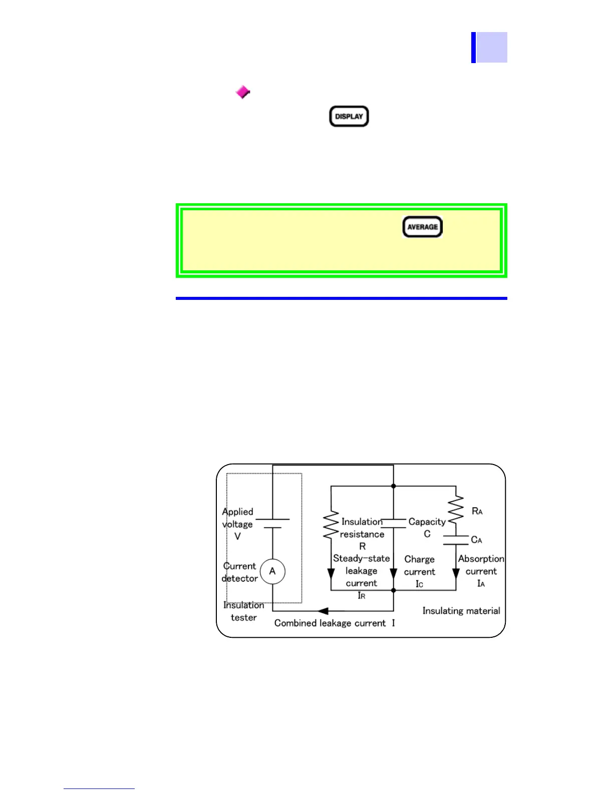
3.2.6 Insulation Resistance Measurement
Basis
When a high DC voltage is applied to an
object under test, a leakage current flows.
The insulation resistance tester measures
the applied voltage V and the combined
leakage current I and then calculates the
insulation resistance R.
Calculation formula R = V/I
I
C and IA gradually decrease after the volt-
age is applied.
Holding data after measurement
If the indication is unstable, press the key. The
average of the measurements is shown.
[< 1.00 nA] means "below 1.00 nA."