8.1 External Input/Output Connector and Signals
92
• The 0ADJ signal should be asserted (ON) for at least 10 ms.
• The connector's frame is connected to the instrument's rear panel (metal portions) as well
as the power inlet's protective ground terminal.
When switching panel load operation using commands or key operation, fix pins 4 and 5
as well as 22 and 23 to ON or OFF.
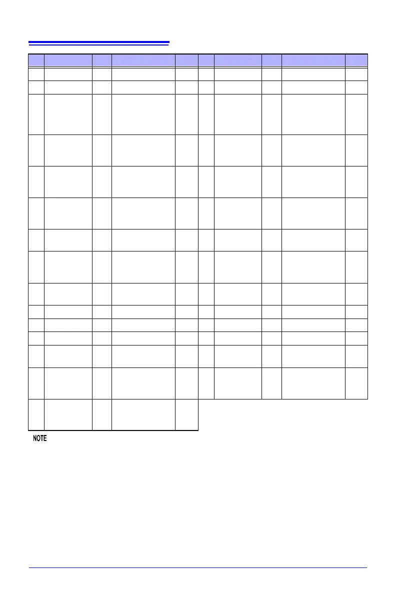
5 LOAD3 IN Panel load Level 24 (Reserved) - - -
6 (Reserved) - - - 25 (Reserved) - - -
7 (Reserved) - - - 26
PRINT
IN1
IN
Printing of
measured values
General-pur-
pose input
Edge
8 ISO_5V
appli-
cable
Isolated power
supply +5 V
(-5 V) output
-27ISO_COM-
Isolated
common signal
ground
-
9ISO_COM -
Isolated
common signal
ground
-28 EOM OUT
End of
measurement
Level
10 ERR OUT
Measurement
fault
Level 29
INDEX,
BCD2-0,
RNG_OUT0
OUT
Analog
measurement
finished
Level
11 HI, HILO OUT
Comparator
judgment
Level 30 IN OUT
Comparator
judgment
Level
12
LO,
BCD2-1,
RNG_OUT1
OUT
Comparator
judgment
BCD
Level 31
BCD2-2,
RNG_OUT2
OUT BCD Level
13
BCD2-3,
RNG_OUT3
OUT BCD Level 32 BCD3-0 OUT BCD Level
14 BCD3-1 OUT BCD Level 33 BCD3-2 OUT BCD Level
15 BCD3-3 OUT BCD Level 34 BCD4-0 OUT BCD Level
16 BCD4-1 OUT BCD Level 35 BCD4-2 OUT BCD Level
17 BCD4-3 OUT BCD Level 36
BCD5-0,
BCD1-0
OUT BCD Level
18
OUT0,
BCD5-1,
BCD1-1
OUT
General-pur-
pose output
BCD
Level 37
OUT1,
BCD5-2,
BCD1-2
OUT
General-pur-
pose output
BCD
Level
19
OUT2,
BCD5-3,
BCD1-3
OUT
General-pur-
pose output
BCD
Level
Pin Signal name I/O Function Logic Pin Signal name I/O Function Logic