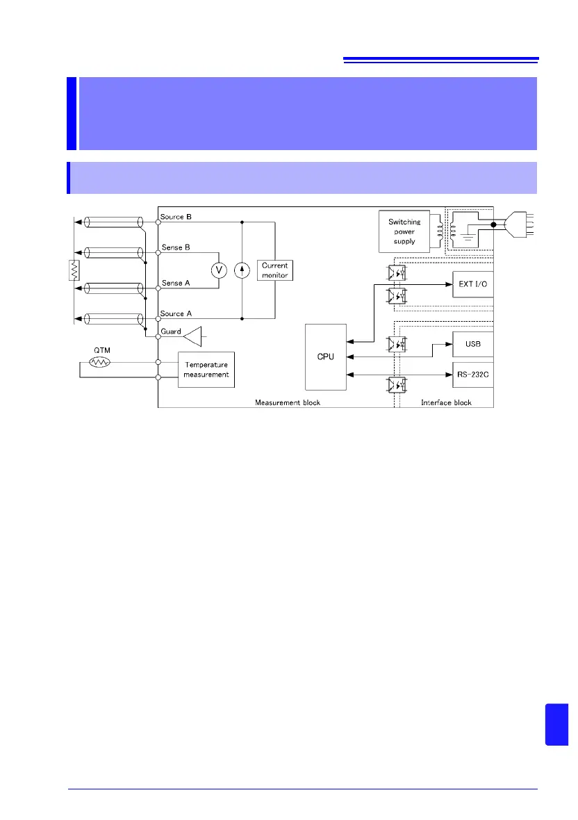
Appendix 1 Block Diagram
A1
Appendix
• Constant current (determined by the measurement range) is applied between the
SOURCE B and SOURCE A terminals while voltage is measured between the SENSE B
and SENSE A terminals. The resistance value is obtained by dividing the measured volt-
age (B) by the constant current flow (A).
• The low-noise voltmeter can perform stable measurement, even with an integration time
of 17 ms (B).
• When measurement starts, the constant current monitor (C) are activated to monitor for
fault conditions while measuring.
• The instrument incorporates a built-in temperature measurement circuit that can be used
to correct resistance measured values according to the temperature when measuring a
target that exhibits a high level of temperature dependence (D).
• The high-speed CPU (E) provides ultra-high-speed measurements and fast system
response.
• Immunity from electrical noise is provided by isolation between the Measurement and
Interface blocks.
EXT I/O is isolated from the USB and RS-232C interfaces. The USB and RS-232C inter-
faces use the same potential as the protective ground. (F).
• The auto-ranging 100-to-240 V switching power supply (G) can provide stable measure-
ments even in poor power quality environments.
Appendix
Appendix 1 Block Diagram