Appendix 10 Making Your Own Measurement Leads
A24
• Wiring resistance in excess of the values
listed in the table to the right may cause a
current fault, making measurement
impossible. When using measurement
current 300 mA ranges, keep the wiring
resistance (cable line resistance, relay
on-resistance) as well as the contact
resistance between the measurement tar-
gets and probe low.
• Since the voltage detection circuit’s input resistance is at least 1 G, the SENSE line wir-
ing resistance can be as high as 1 k without affecting measured values. However, the
wiring resistance should be minimized due to susceptibility to noise.
• Long wires are susceptible to noise, and measured values may be unstable.
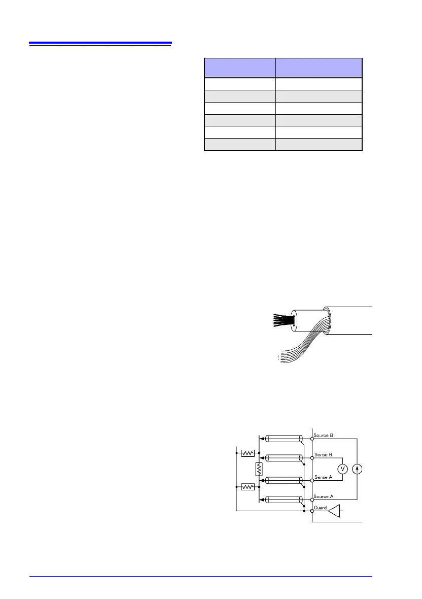
• Extensions should maintain the four-terminal structure. If converted to a two-terminal cir-
cuit in the wiring, correct measurement may not be possible due to the effects of wiring
and contact resistance.
Example that would result in error:
Four-terminal wiring from the instrument to the relay, but two-terminal wiring from the
relay
• After extending measurement leads, confirm operation and accuracy ("Measurement
Specifications" (p.146)).
• If cutting the ends off of HIOKI measurement leads,
make sure that the shield does not touch the center
conductor of the SOURCE A, SENSE A, SENSE B
and SOURCE B leads. Correct measurement is not
possible with a shorted lead.
• Do not connect the end of the shielding wire to a
ground or other terminal. Doing so will create a
ground loop, making the instrument more suscepti-
ble to noise. Keeping the shielding wire away from
the center conductor, process the ends of the leads
so that they do not come into contact with nearby
metal objects.
• Do not apply a current of 1 mA or more to the
GUARD terminal. This terminal is not for guard-
ing network resistance measurements.
Range Wiring resistance and
contact resistance
30 m, 300 m 2
3 70
30 100
300 2 k
3 k 700
30 k to 3 M 2 k
Center
conductor
Shielded
wiring
Example of defeated guard measurement
 Loading...


