8.2 Timing Chart
97
8
Each signal level indicates the ON/OFF state of a contact. When using the current source
(PNP) setting, the level is the same as the EXT I/O pin voltage level. When using the cur-
rent sink (NPN) setting, the high and low voltage levels are reversed.
(1) External trigger [EXT] setting (EOM output hold)
• Do not apply a TRIG signal while measuring (when the INDEX signal is OFF) (the signal
will be retained only once).
• When changing settings such as measurement range, allow about 300 ms processing
time before applying a TRIG signal.
• When not displaying the Measurement screen and while error messages are being dis-
played, input signals are disabled.
• HI, IN, LO, ERR and BCDm-n signal output is finalized before the EOM signal changes to
ON. However, if the controller’s input circuit response is slow, it may be necessary to
insert wait processing after EOM=ON is received until the judgment results are acquired.
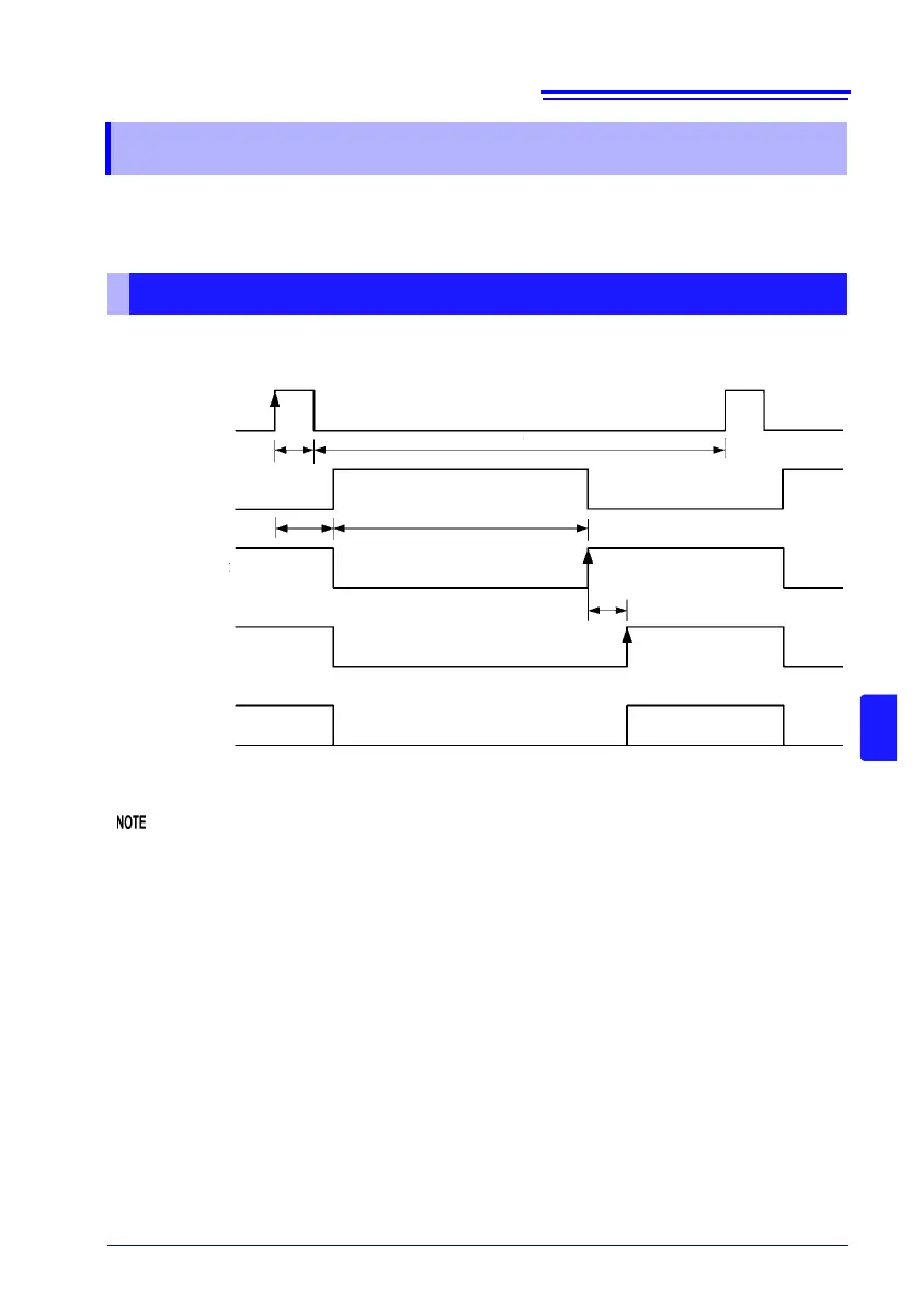
8.2 Timing Chart
From Start of Measurement to Acquisition of Judgment Results
ON
OFF
t0 t1
t3
INDEX
EOM
OFF
OFF
OFF
ON
ON
HI, IN, LO,
ERR, BCDm-n,
TRIG
OFF
OFF
OFFON/OFF
t2
t4
Measurement
Measurement
processing
RNG_OUT0 to 3