Appendix 10 Making Your Own Measurement Leads
A23
Appendix
Recommended Measurement Lead Specifications
Example: UL1354, UL1631, UL1691
* Teflon is a registered trademark of E. I. du Pont de Nemours and Company.
Before Wiring
See: "Appendix 7 Unstable Measured Values" (p. A13)
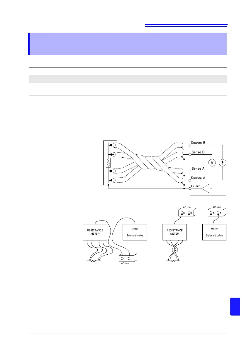
• Use shielded wiring for
measurement leads and
connect the shield potential
to the instrument’s GUARD
terminal. Use the GUARD
potential to shield probes
and near the measurement
target.
Twist the four wires together
and keep loop area small.
• Keep measurement
leads and the mea-
surement target
away from high-cur-
rent, high-voltage,
and high-frequency
wires (withstanding
voltage testers,
power cords, motors,
solenoid valves).
• When using two or more RM3544 units, do not group the wires from multiple instruments
together. Induction phenomena may cause measured values to become unstable.
• Refer to the block diagram (p. A1) for internal circuit details.
Appendix 10 Making Your Own Measurement
Leads
Conductor resistance
500 m/m or less
Capacitance
150 pF/m or less
Cable dielectric material
Polyethylene (PE), Teflon* (TFE), polyethylene foam (PEF)
Insulation resistance at least 10 G (Performance value)
Wiring Diagram
Static shielding
Poor example Good example
Power supply on a separate circuit
The same inlet
is used.
Measurement leads are
close to power supply wires.