1.4 Screen Organization and Operation Overview
21
1
The instrument’s screen interface consists of a Measurement screen and various Settings
screens.
The screen examples in this guide appear reversed (black on white) for best visibility on the
printed page. However, the instrument screens can actually be displayed only as white
characters on black background.
Display of information other than measured values
(For more information, see "Confirming Measurement Faults" (p.38).)
* To treat current faults (when the source wiring is open) as over-range events, change the
current fault output mode setting. (p.40)
1.4 Screen Organization and
Operation Overview
Display Description
+OvrRng
-OvrRng
Over-range
- - - - -
Not measured, or broken connection in mea-
surement target *
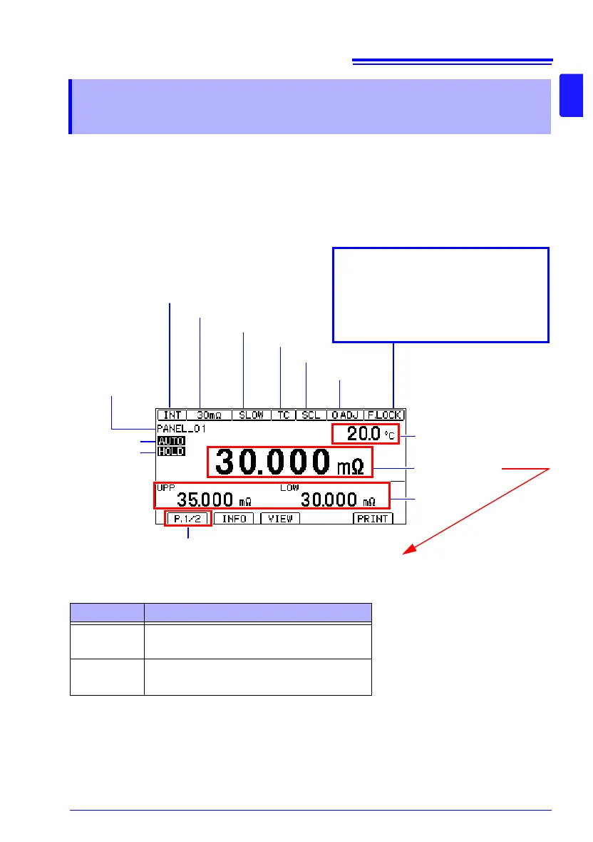
Trigger source (INT/EXT)
Measurement range
TC (ON)
0ADJ (ON)
Auto range
Key lock state or remote state
Cancel the key lock state or remote
state by pressing and holding the
MENU key.
F.LOCK : All operations prohibited.
M.LOCK: Menu operations prohibited.
RMT : Remote state
Judgment value
Switched with the VIEW key
(No display / temperature /
pre-calculation resistance
value)
Page switching
Measurement screen layout
Hold state
Scaling (ON)
Measurement speed
Number and name
of loaded panel
Measured value